CURRENT COLLECTION OF INSTRUMENTATION AND TELEMETRY COMPONENTS
SATURN I BLOCK I ANTENNA
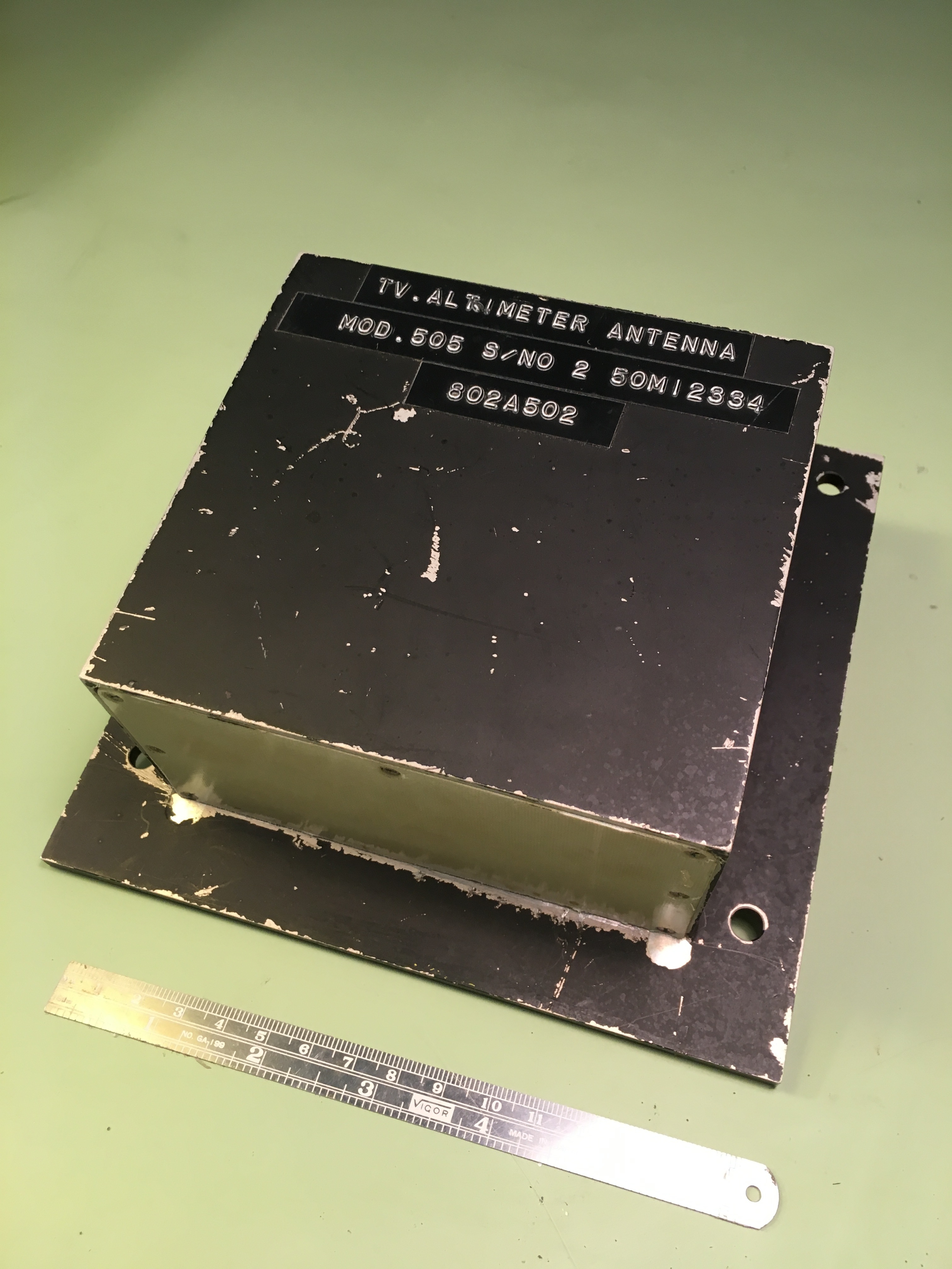
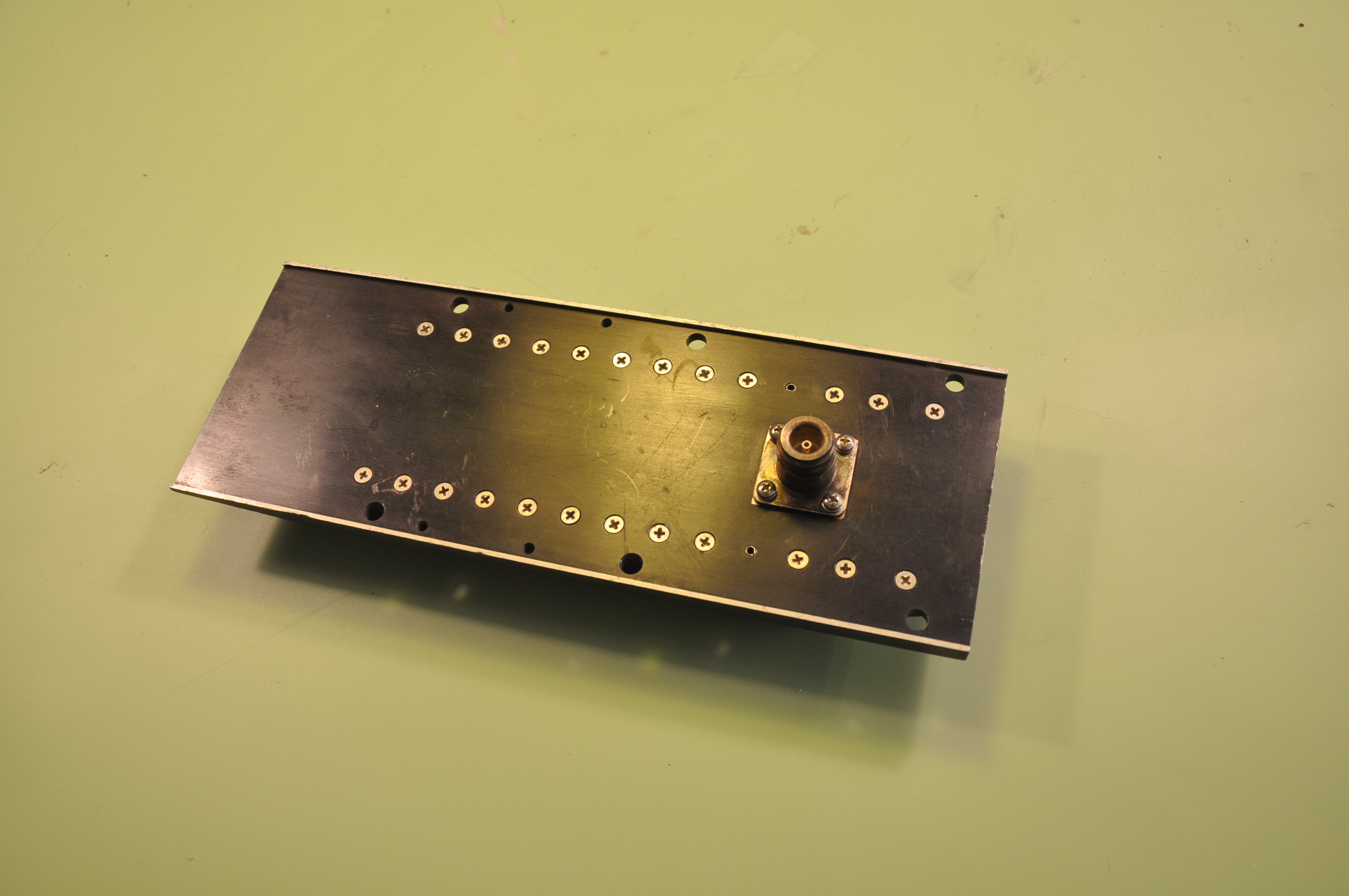
An antenna I believe to be Saturn I Block I, but I have never been able to verify this.
The labels on the antenna above read
- TV Altimeter Antenna
- Mod. 505 S/No 2 50M12334
- 802A502
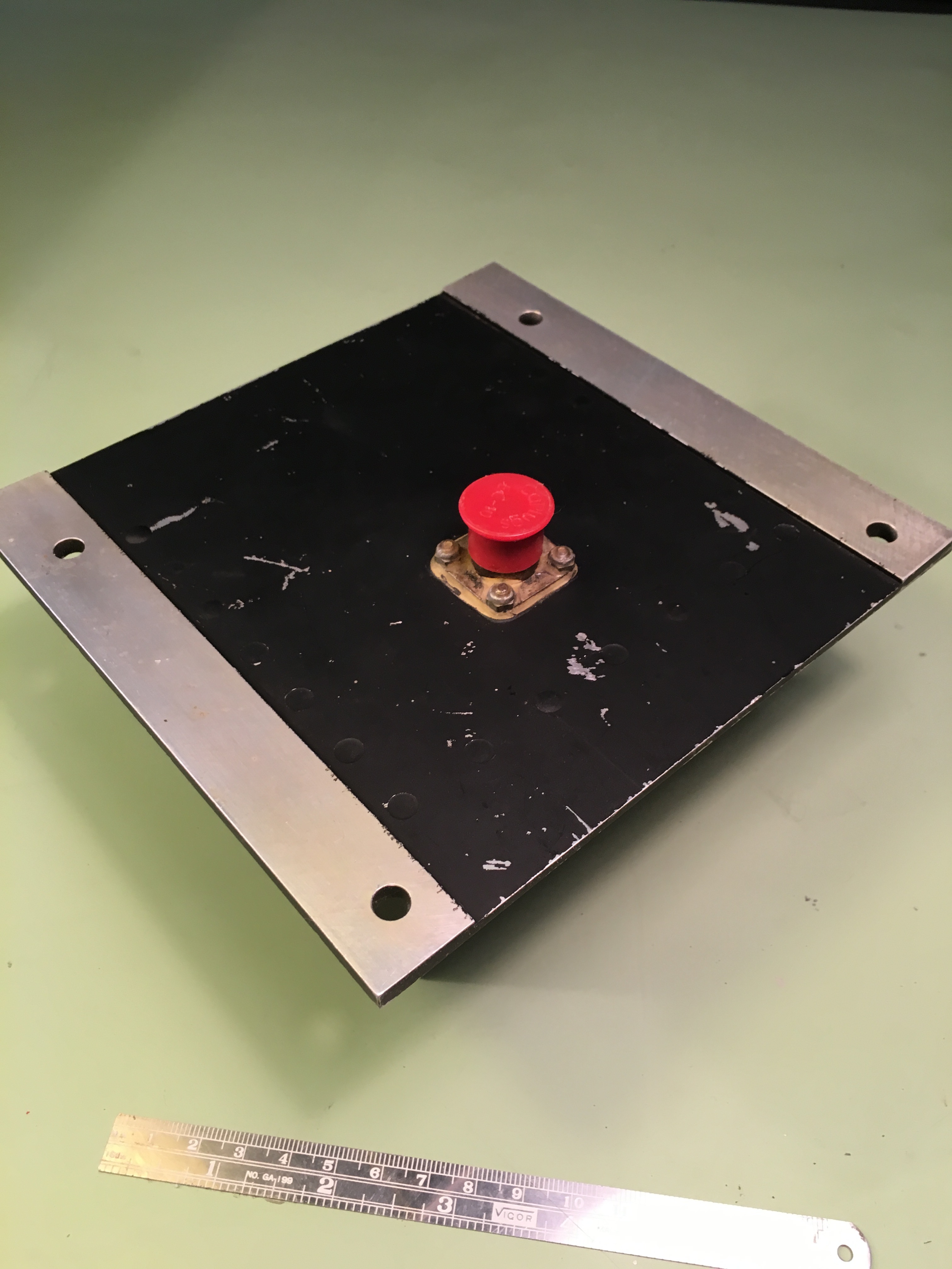
Antenna's Reverse
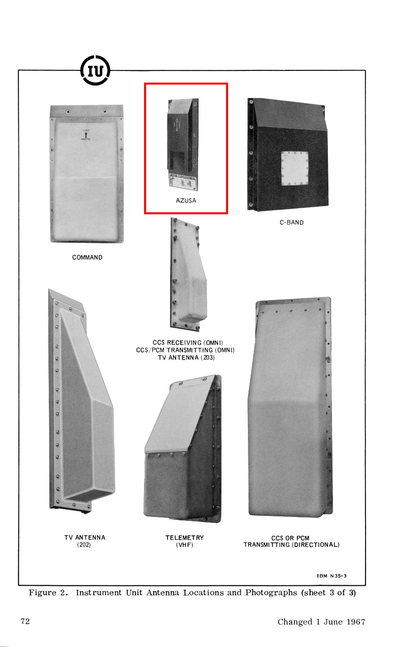
Instrument Unit Antennas
SATURN IB/V INSTRUMENT UNIT AZUSA RADAR ANTENNA
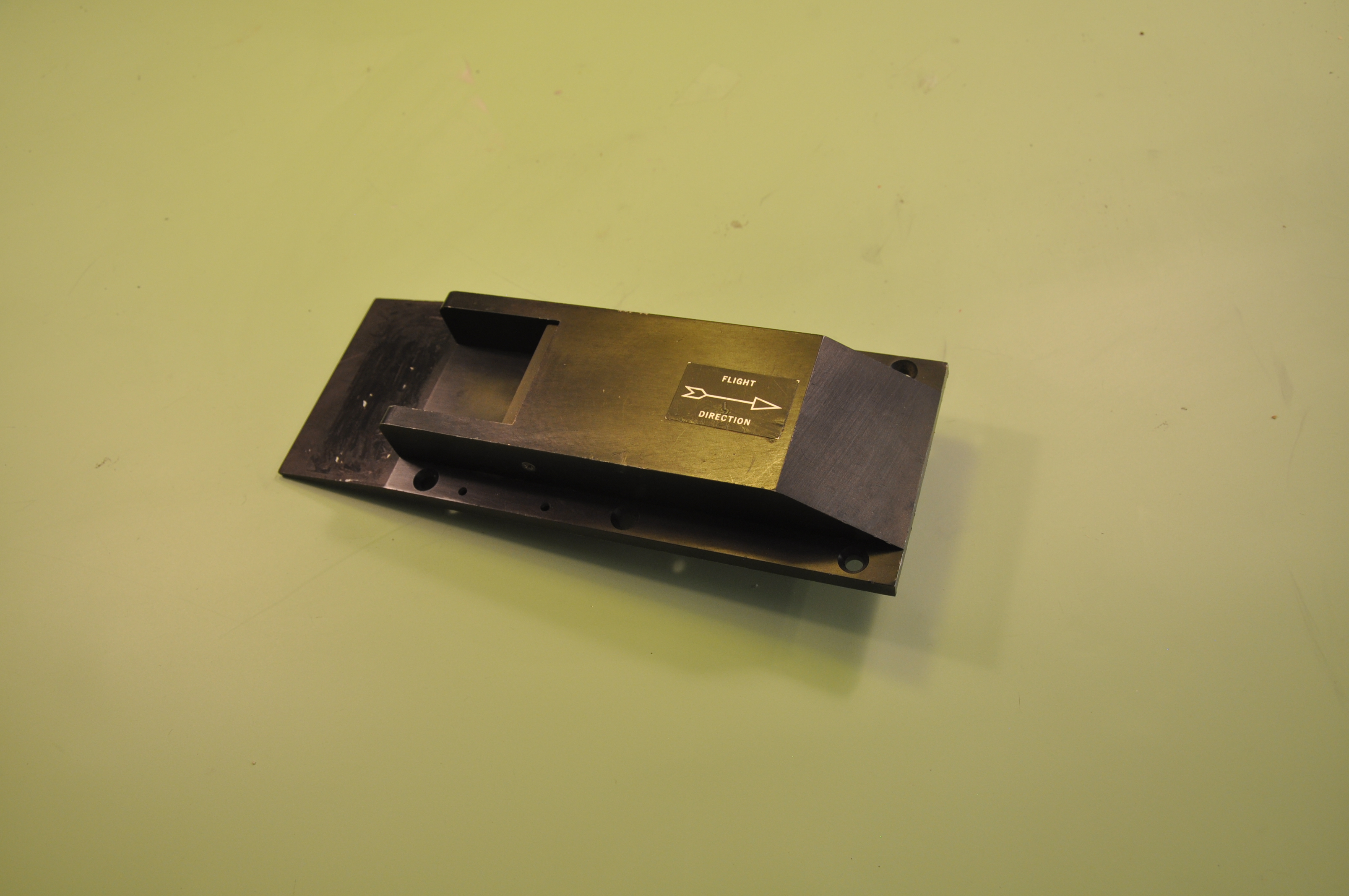
Saturn Instrument Unit Azusa radar antenna.
The Azusa antenna received a cw C-Band carrier, frequency modulated by range signals, from a ground-based Azusa tracking station. The Azusa transponder simultaneously retransmitted an offset carrier frequency modulated by the range signals to the ground tracking station. Range measurement was accomplished by measuring the phase delay between the received and transmitted modulation frequencies at the ground station. The remaining measurements, to determine position, were obtained by measuring the phase delay between the received and transmitted carrier frequency.
Antenna's Reverse
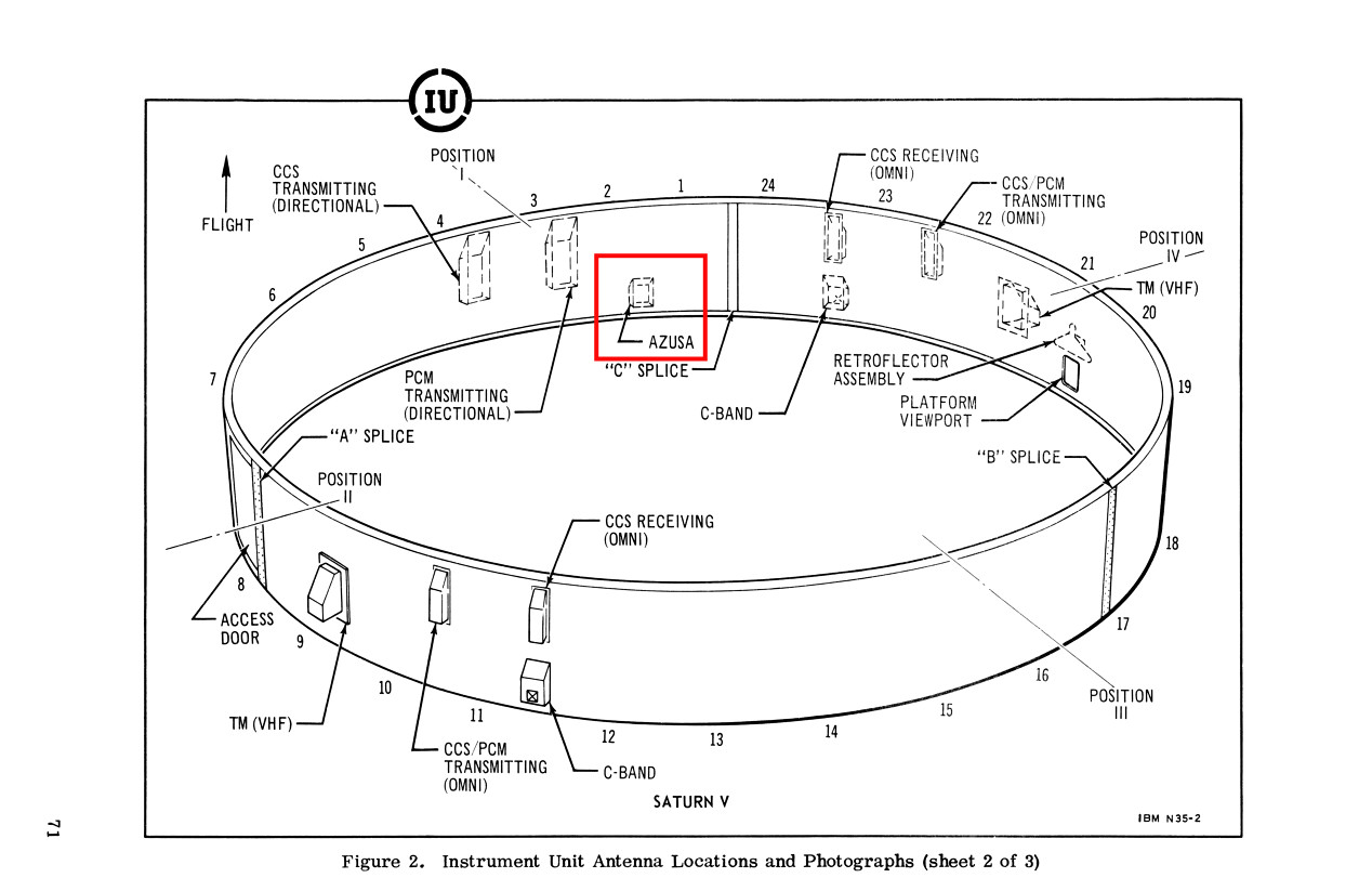
Azusa Radar Antenna Location
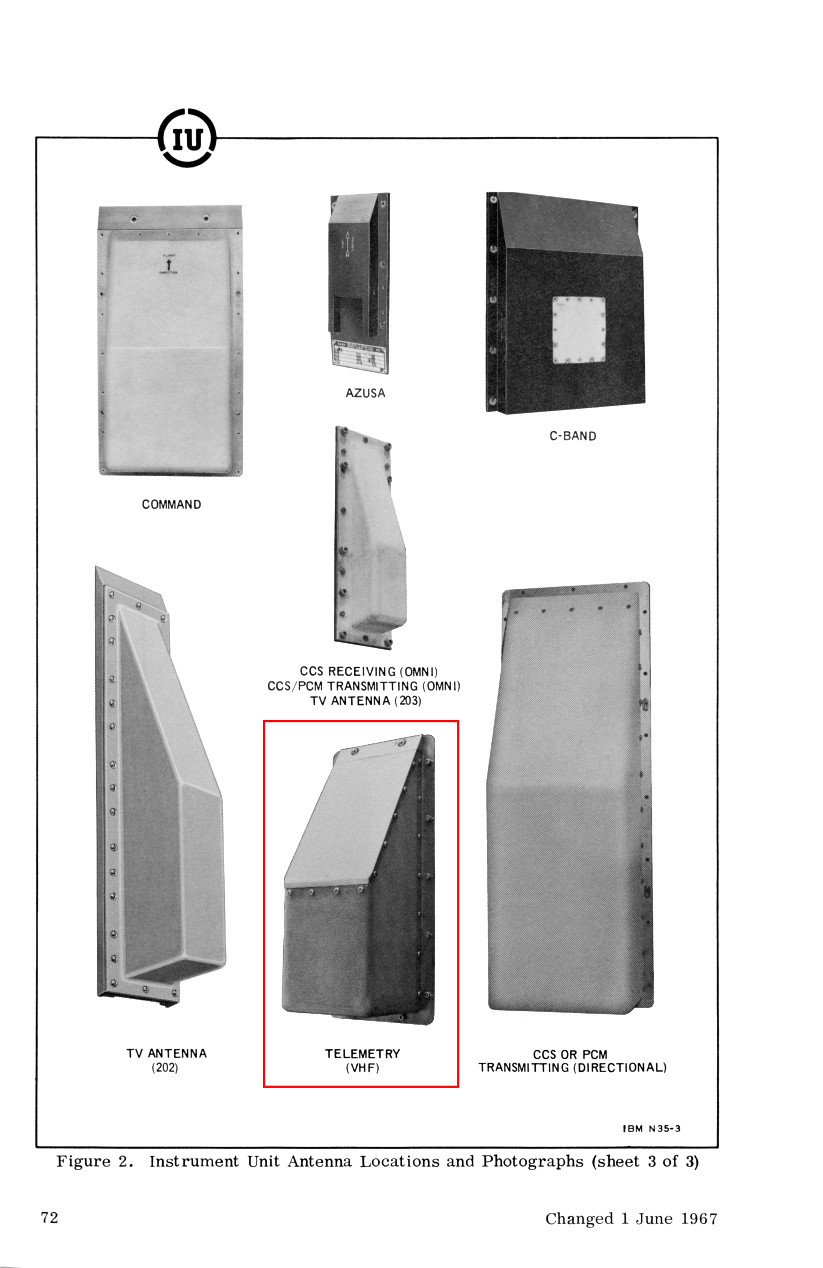
Instrument Unit Antennas
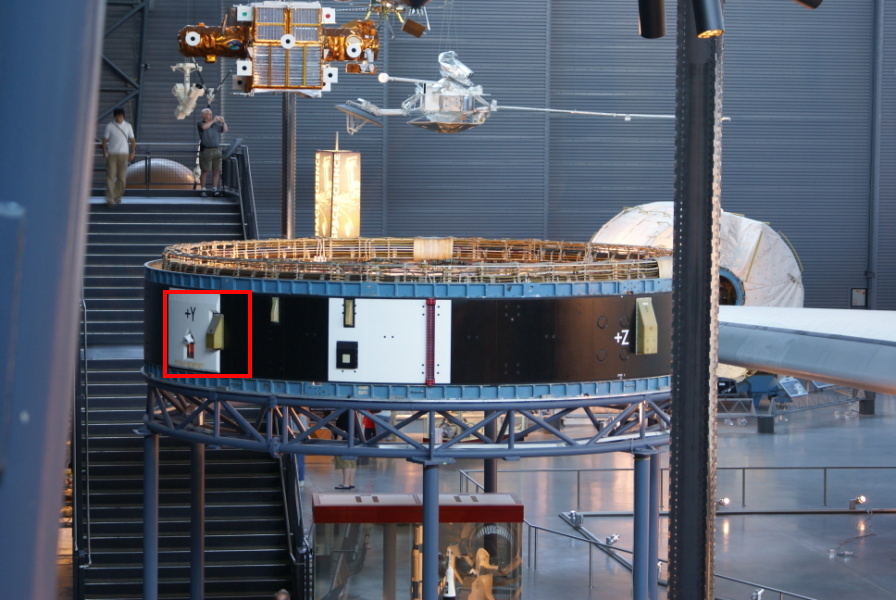
VHF Telemetry Antenna in +Y Location on Udvar-Hazy Instrument Unit
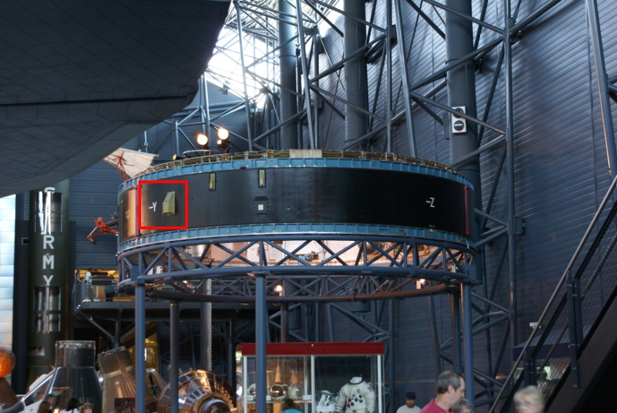
VHF Telemetry Antenna in -Y Location on Udvar-Hazy Instrument Unit
SATURN V INSTRUMENT UNIT VHF TELEMETRY ANTENNA

Saturn V Instrument Unit VHF telemetry antenna. This is a transmit-only, highly-directional telemetry antenna. Two such antennas were mounted on the IU, one on each side.
The antenna transmitted signals from the RF Transmitter Assemblies as a frequency-modulated VHF carrier with frequency-intelligent data. The output carrier from the transmitter subassembly was processed through a power amplifier and low-pass output filter.
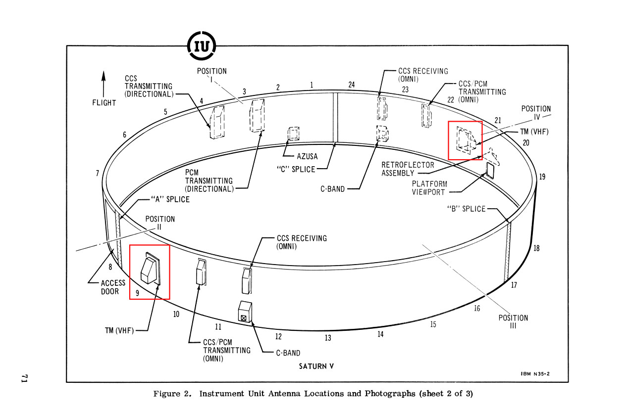
VHF Telemetry Antenna Location
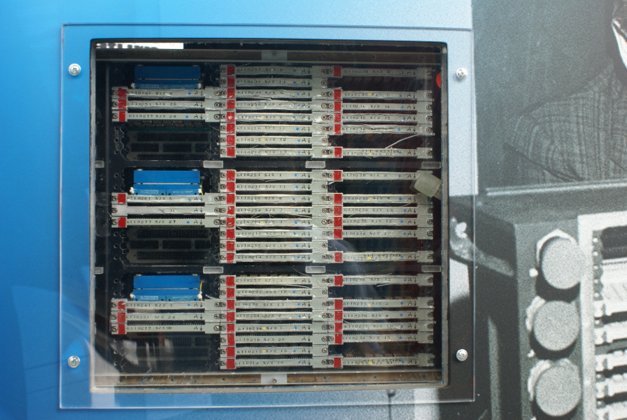
IU Launch Vehicle Digital Computer with logic cards
A group of IU LVDC logic cards
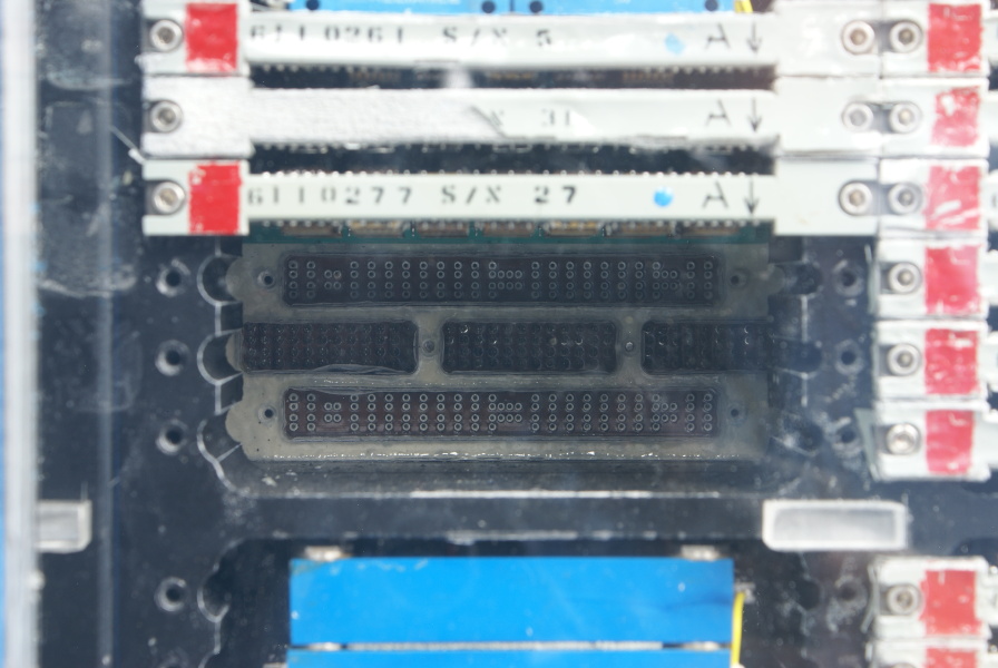
IU LVDC backplane which logic card plug into
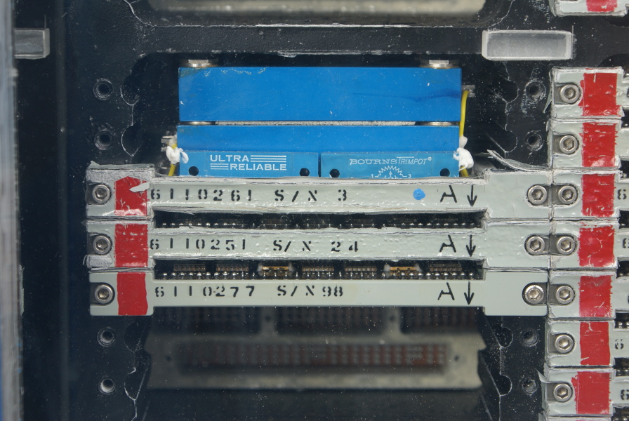
SATURN INSTRUMENT UNIT LAUNCH VEHICLE DIGITAL COMPUTER PAGE LOGIC CARD
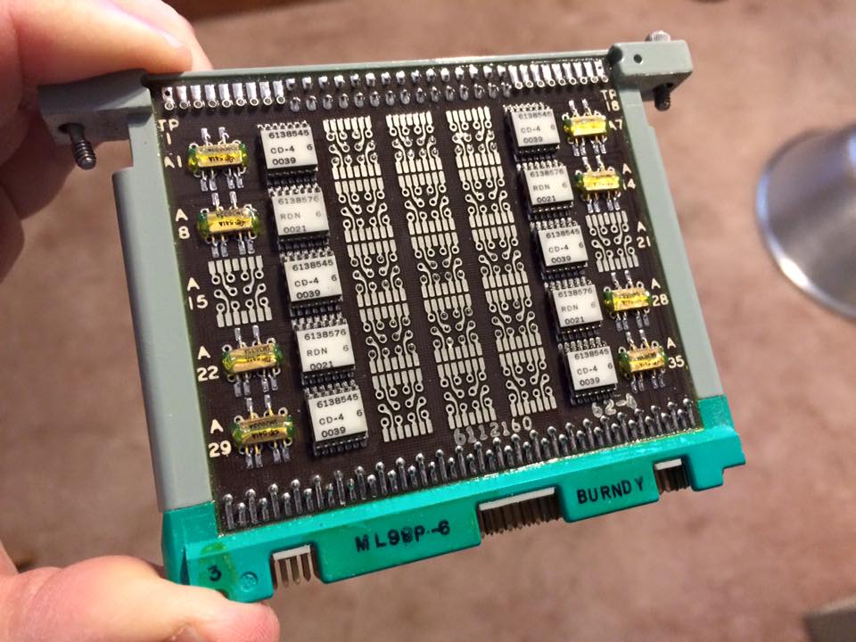
Saturn IB/V Instrument Unit (IU) Launch Vehicle Digital Computer page logic card. These boards formed the logic section of the LVDC computer. Each board could hold up to 35 logic chips; this one has 20.
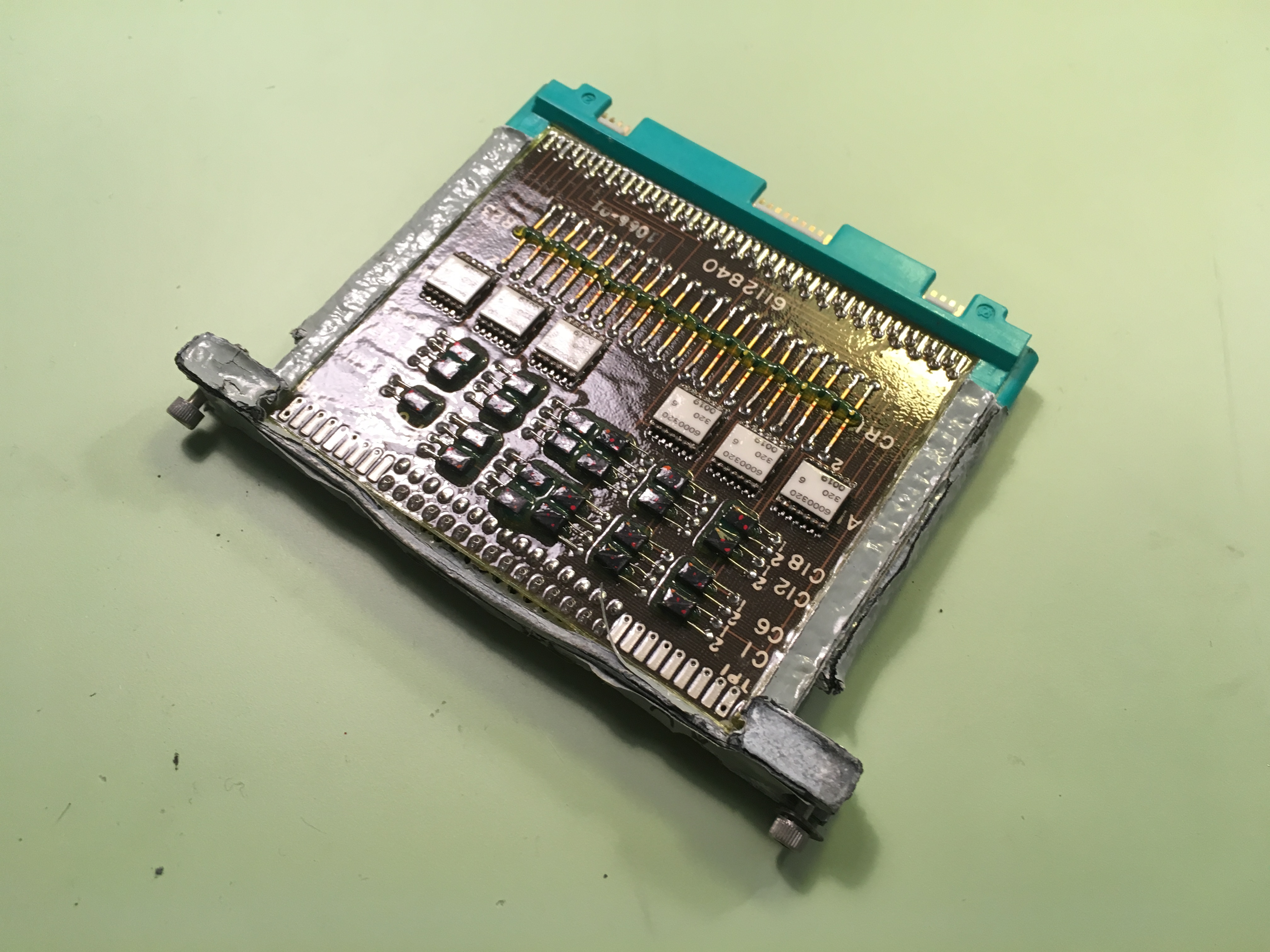
Another page card appears below, this one exhibiting corrosion of the magnesium alloy frame which provided a heat conduction path to the water cooling loop using in the LVDC. This type of corrosion common on existing page cards.
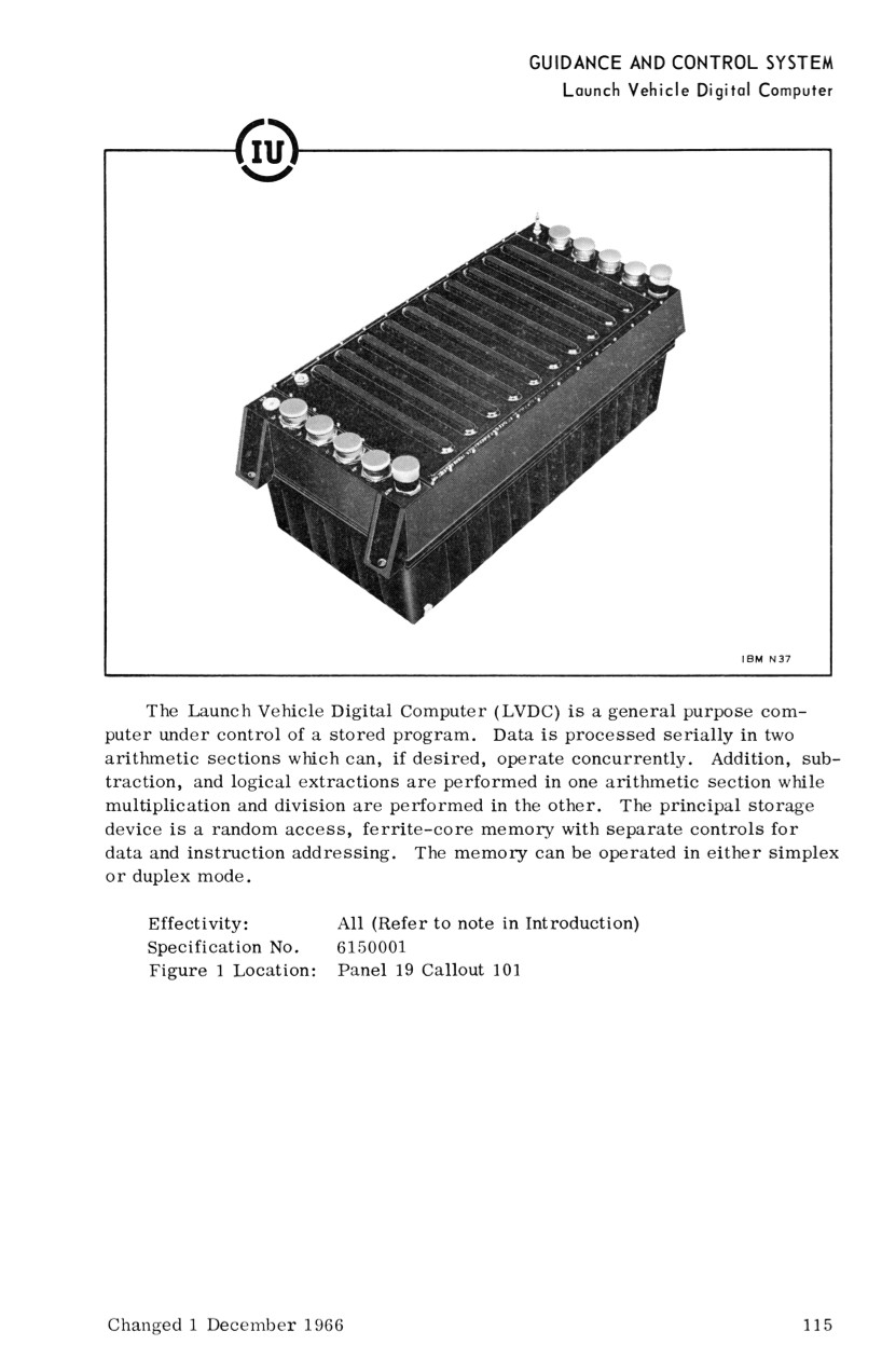
Instrument Unit Launch Vehicle Digital Computer
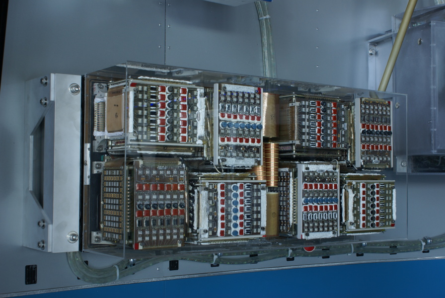
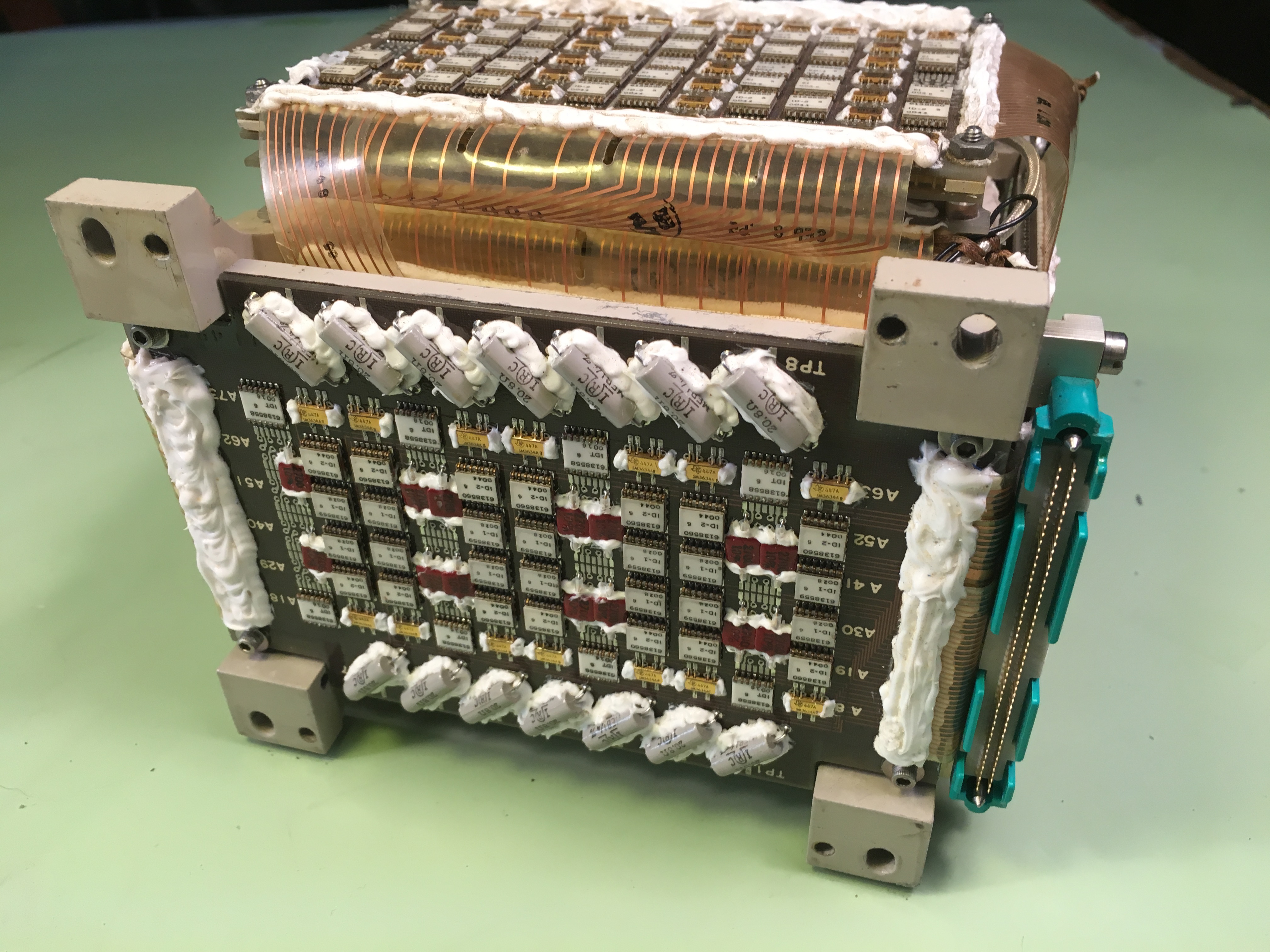
Magnetic core memory modules installed in an IU Launch Vehicle Digital Computer

An IU LVDC memory module in situ
SATURN INSTRUMENT UNIT LAUNCH VEHICLE DIGITAL COMPUTER MAGNETIC CORE MEMORY MODULE
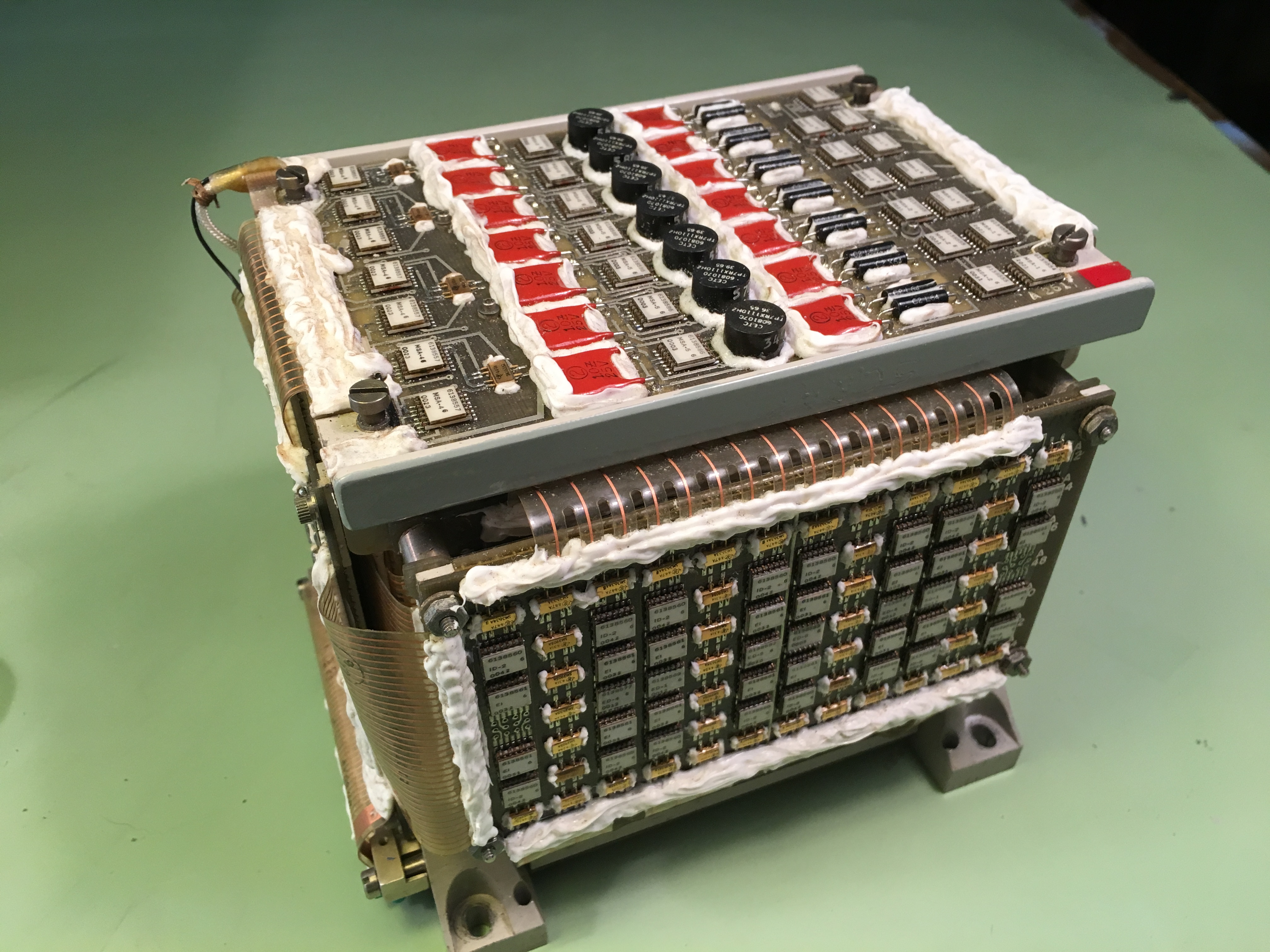
The LVDC's principal storage device was random-access, ferrite-core memory modules with separate controls for data and instruction addressing. Each memory module provided 4096 words of random access memory and could be operated in either simplex or duplex mode.
There were 8 memory modules in the LVDC computer. Memory was in the form of 13 bit syllables with a 14th bit providing parity.
Instrument Unit Launch Vehicle Digital Computer
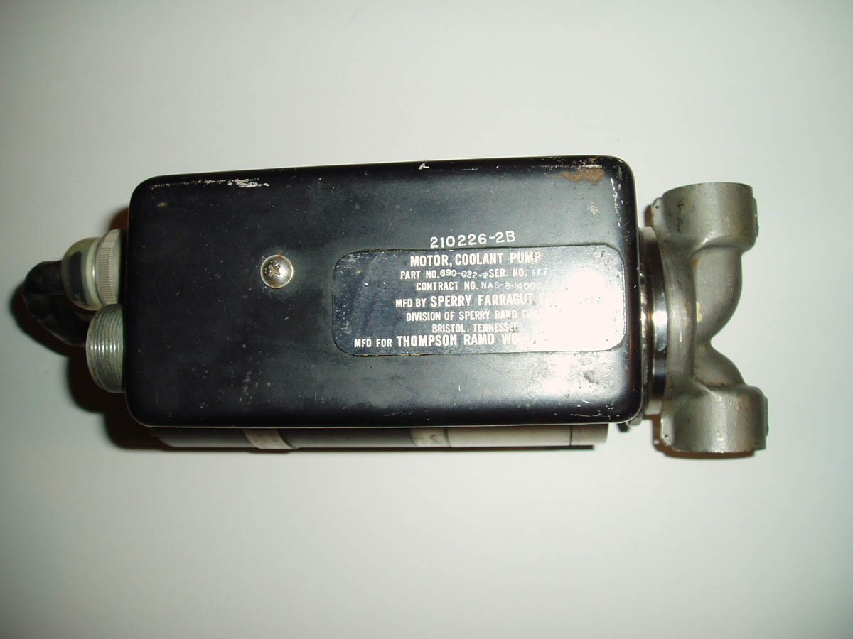
IU Cooling Pump - Top
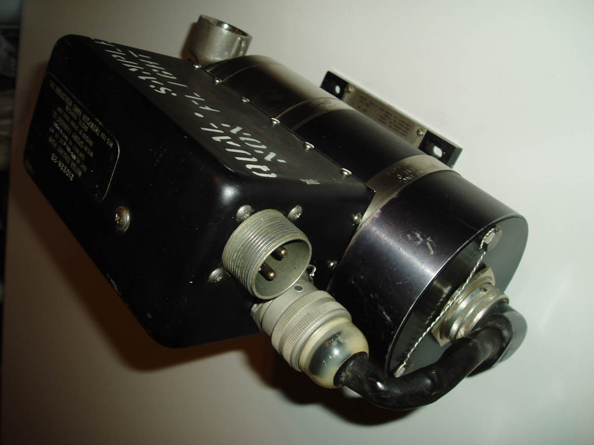
Pump Fluid/Electrical Interface Connectors
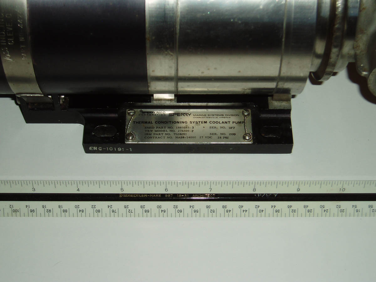
Label Plate
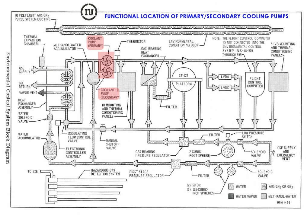
Functional Location of Primary/Secondary Pumps
SATURN INSTRUMENT UNIT COOLANT PUMP
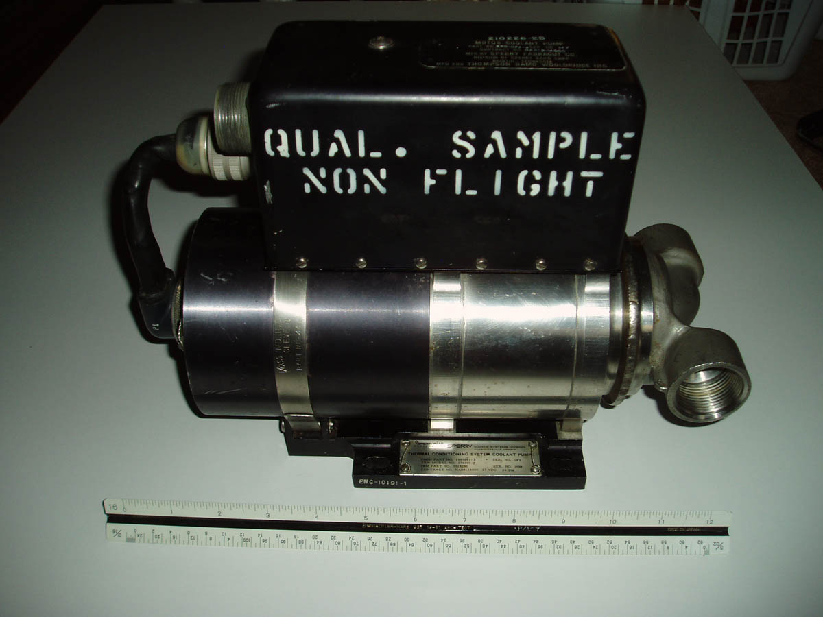
Saturn IB/V Instrument Unit (IU) Coolant Pump used to circulate water/methanol solution through the thermal conditioning system of the IU. The unit consists of an electrical drive motor and centrifugal pump which is designed to operate for 1000 hours continuously flowing coolant at a circulating temperature of 59 degrees F. A subsystem of the Environmental Control System (ECS), the pump was designed to maintain an acceptable operating environment for the IU equipment during preflight and flight operations. One Coolant Pump was used on S-IU-201-205/501-502. Onboard S-IU-206 and subsequent launch vehicles, and S-IU-503 and subsequent 2 pumps were used. The latter were provided with a standby pump to improve the probability that coolant flow was maintained through flight.
The Instrument Unit was a cylindrical structure installed on top of the S-IVB stage on Saturn IB and Saturn V and contained the guidance, navigation, and control equipment which guided the launch vehicle through its mission trajectory and earth orbits (preceding separation from the Command Service Module). In addition, it contained telemetry, communications, tracking and crew safety systems, along with their supporting electrical power and environmental control systems.
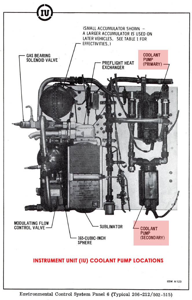
Instrument Unit Panel 6 Showing Location of Primary/Secondary Cooling Pumps