CURRENT COLLECTION OF LIQUID ROCKET PROPULSION SYSTEM ENGINES AND COMPONENTS
Thiokol Reaction Motors Division Engine Collection


YLR-48 Thrust Chamber Obverse
YLR-48
YLR-48
YLR-48

YLR-48
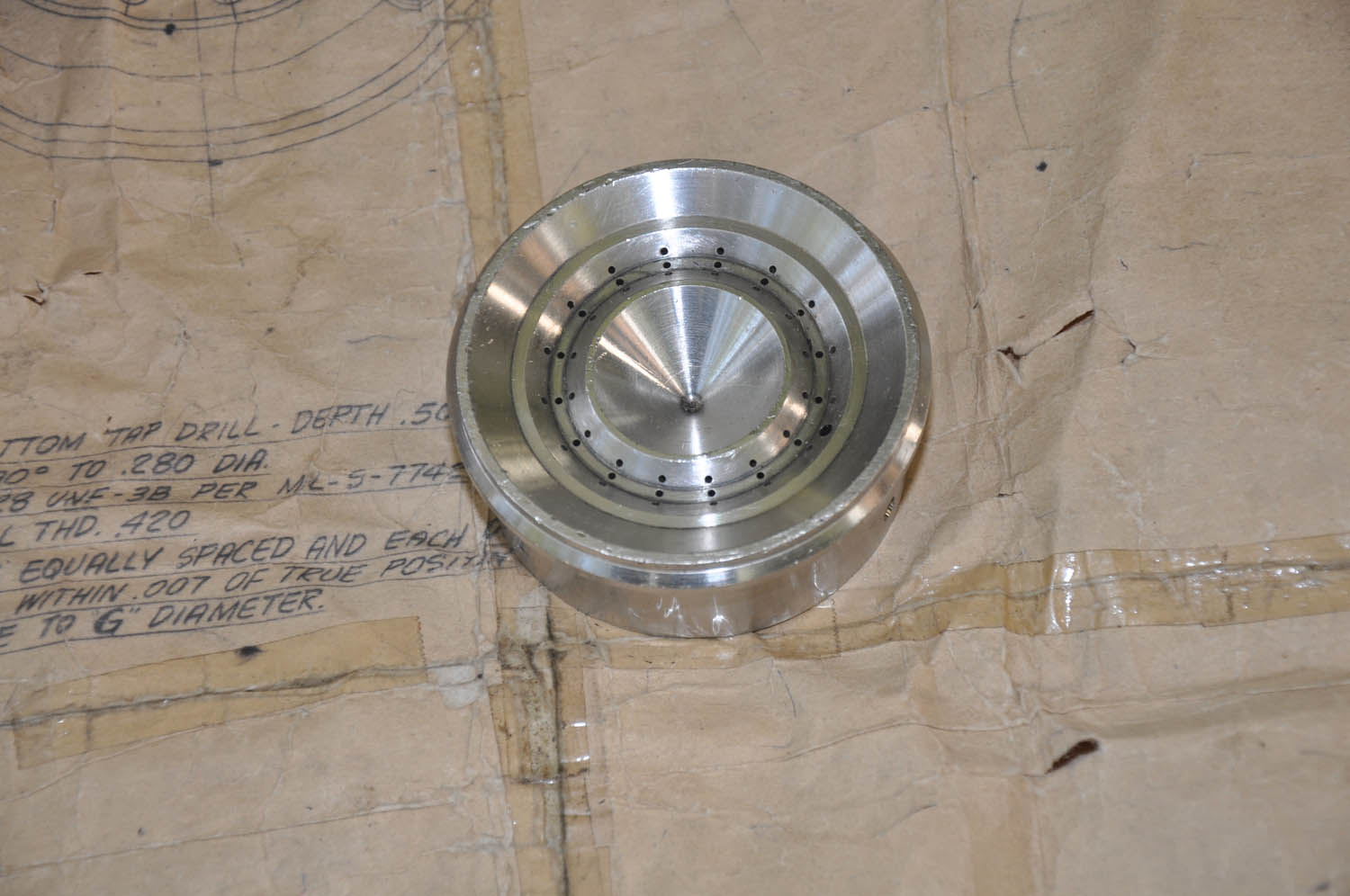
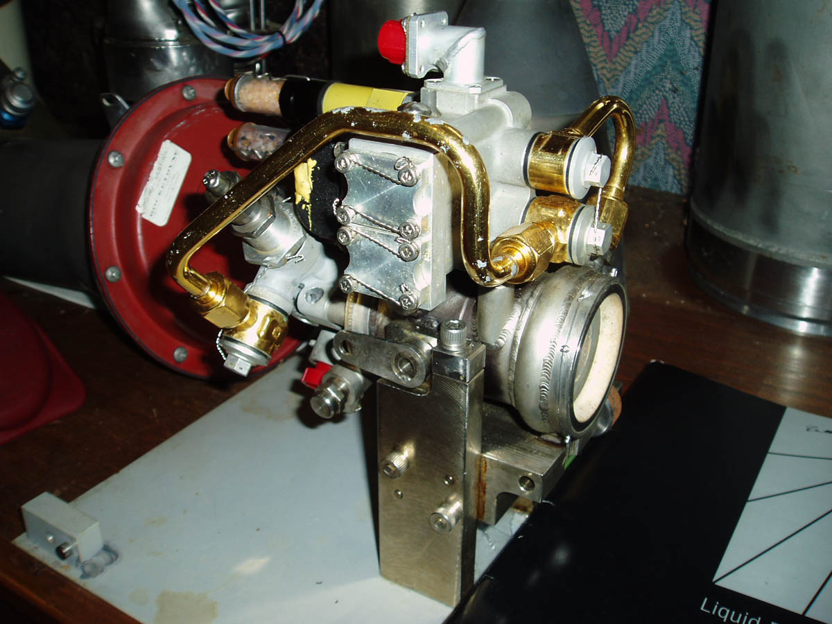
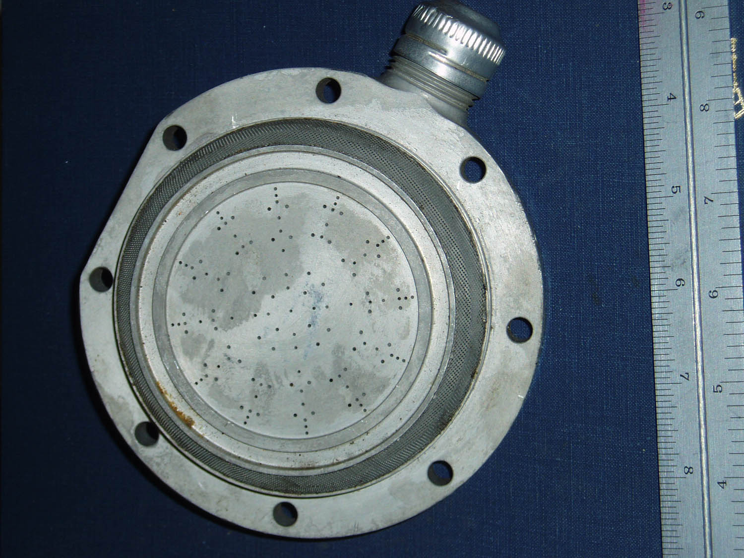
YLR-48 Injector
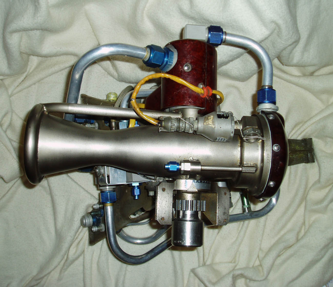
THIOKOL REACTION MOTORS DIVISION YLR-48
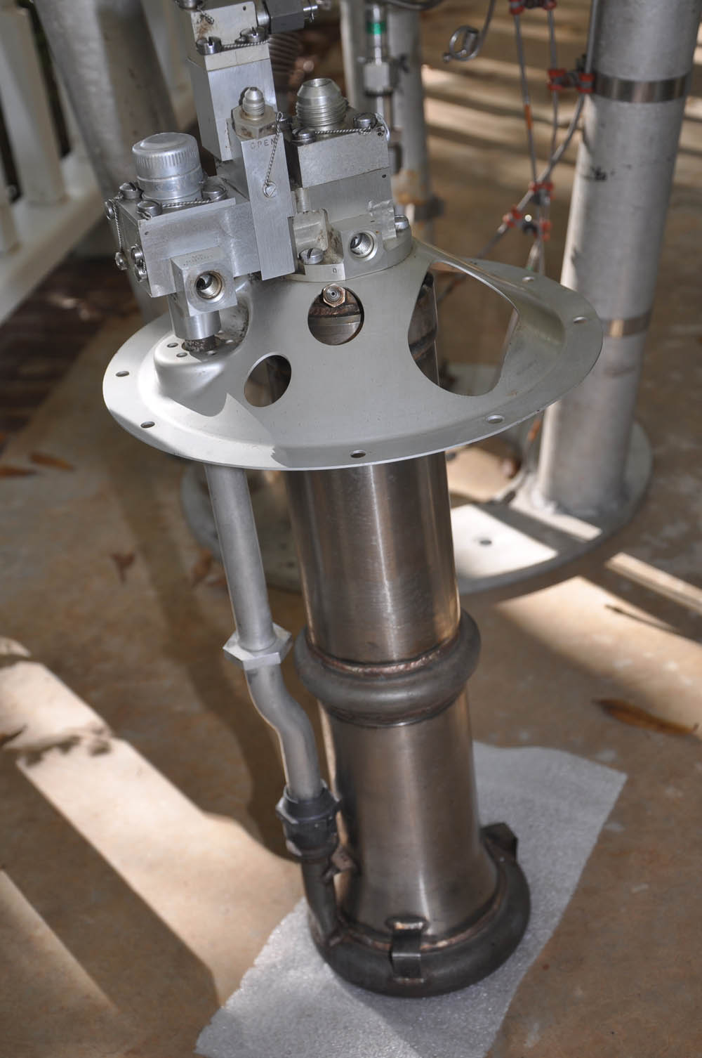
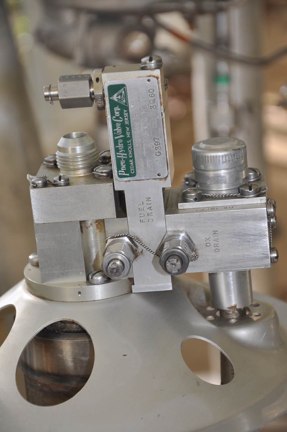
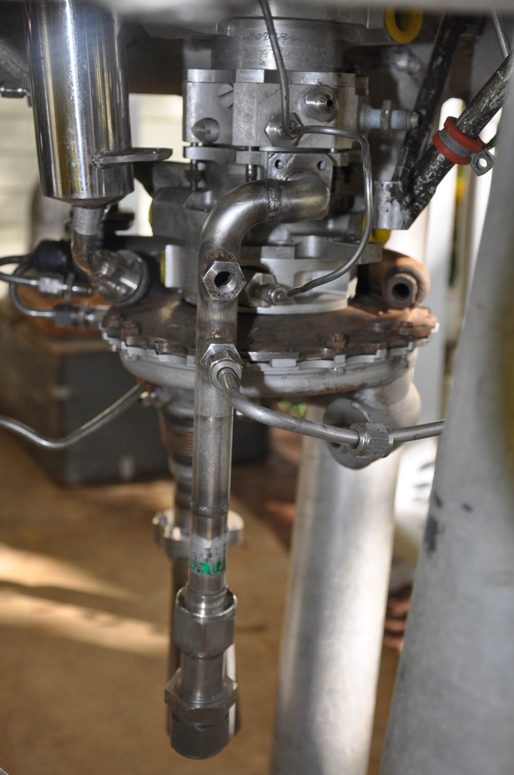
YLR-48 designed and built by Reaction Motors/Thiokol for the Corvus Missile program in 1957. The Corvus was to be an air to surface missile with a range of approximately 100 miles. Corvus was cancelled prior to deployment. The YLR-48 used IRFNA and a mixed Amine fuel. The combination was hypergolic. The propellants were fed to the regeneratively cooled thrust chamber by a small gas generator fed turbopump. The engine provided 1020 pounds of thrust for approximately 3 minutes. This engine is currently undergoing restoration.
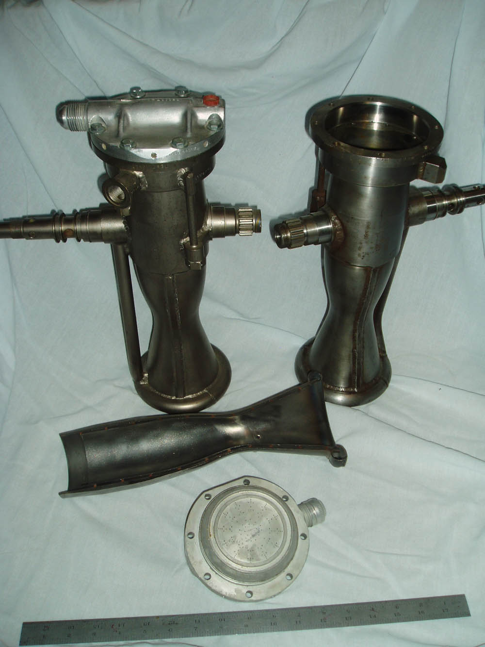
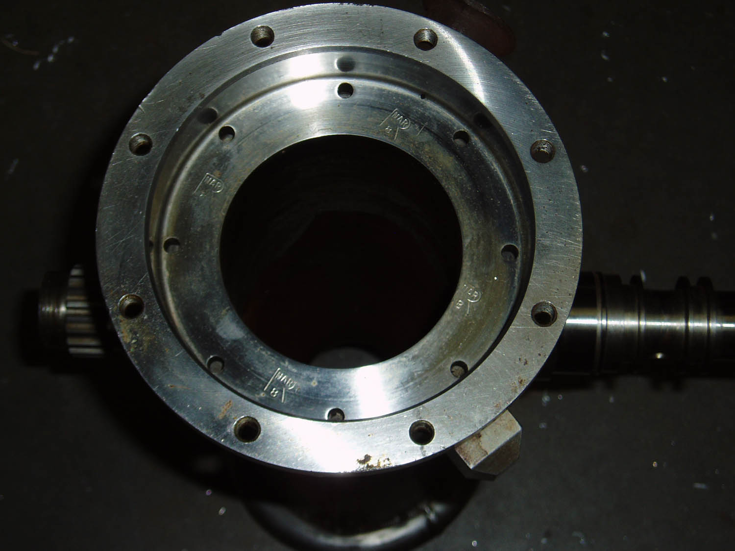
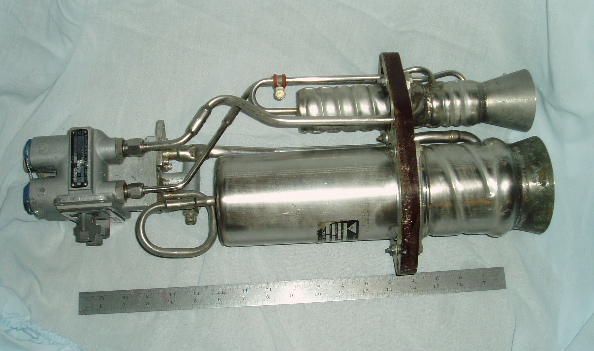
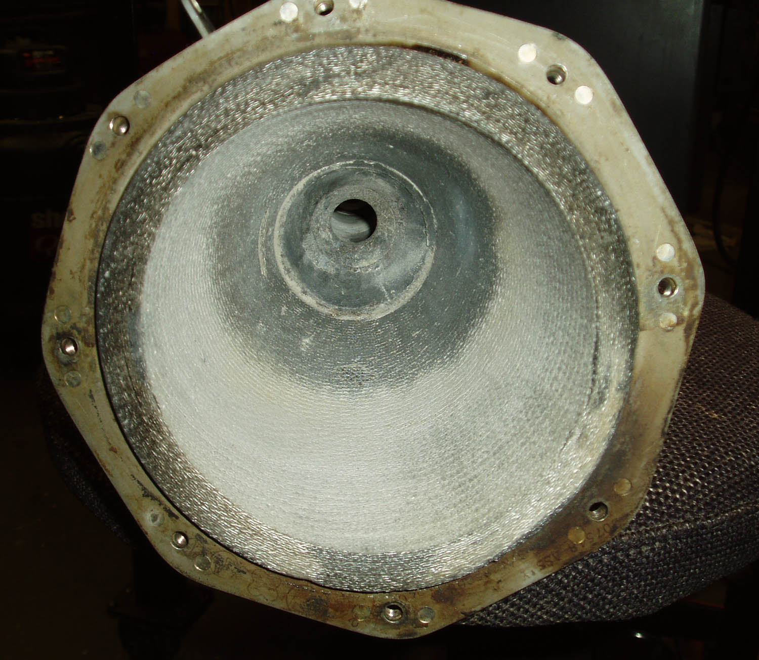
YLR-48 Thrust Chamber Assembly
Thrust Chamber Throat
View 2

View 3

View 4
Test Article
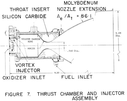
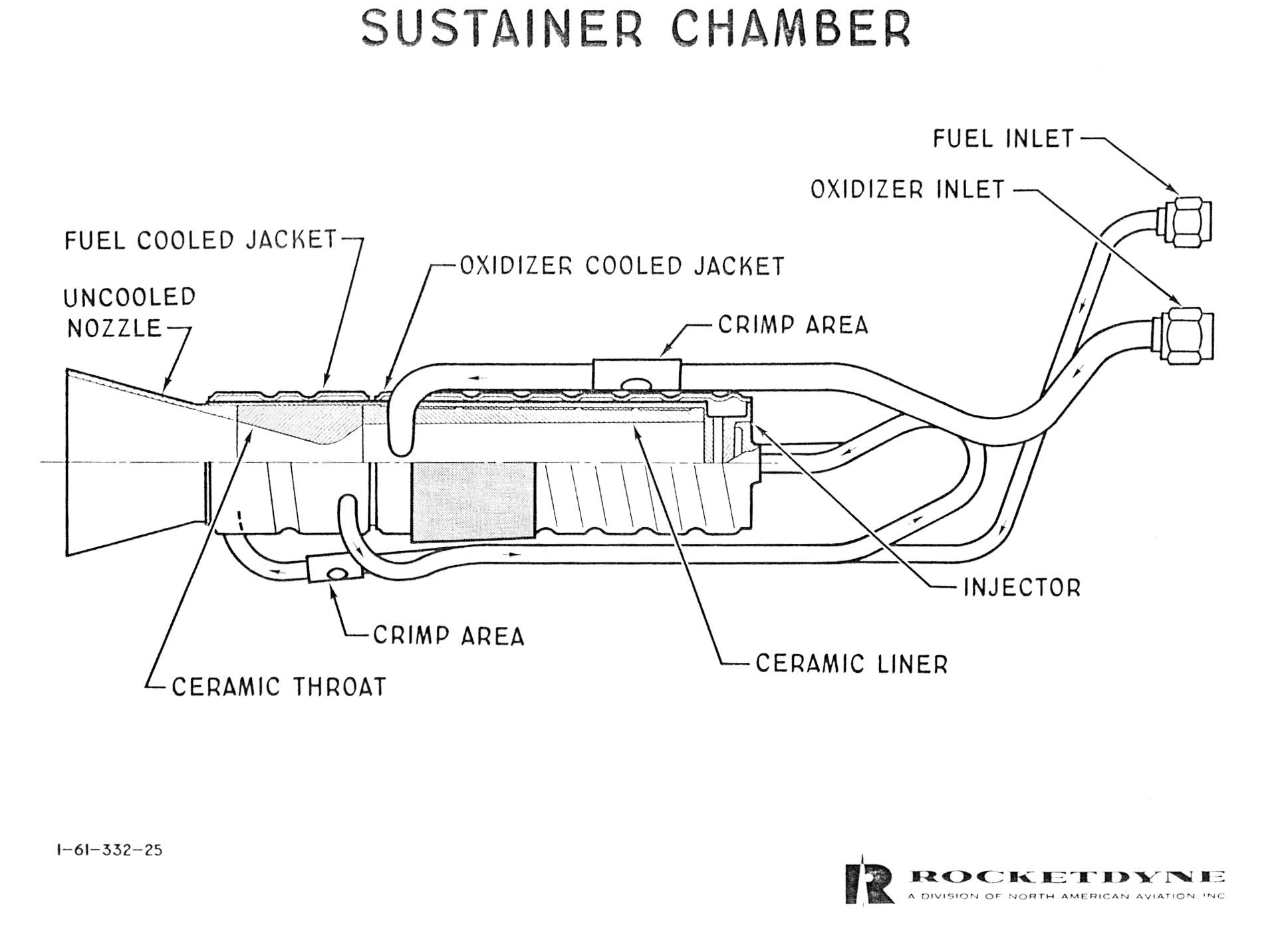
Thrust Chamber Diagram

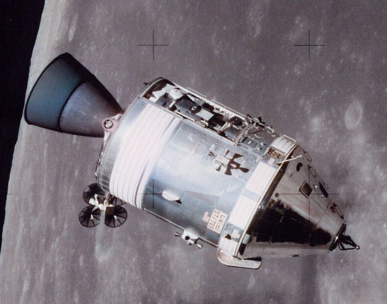
TD-339 Vernier Engine installed on Surveyor S-10 Engineering Model (National Air & Space Museum)
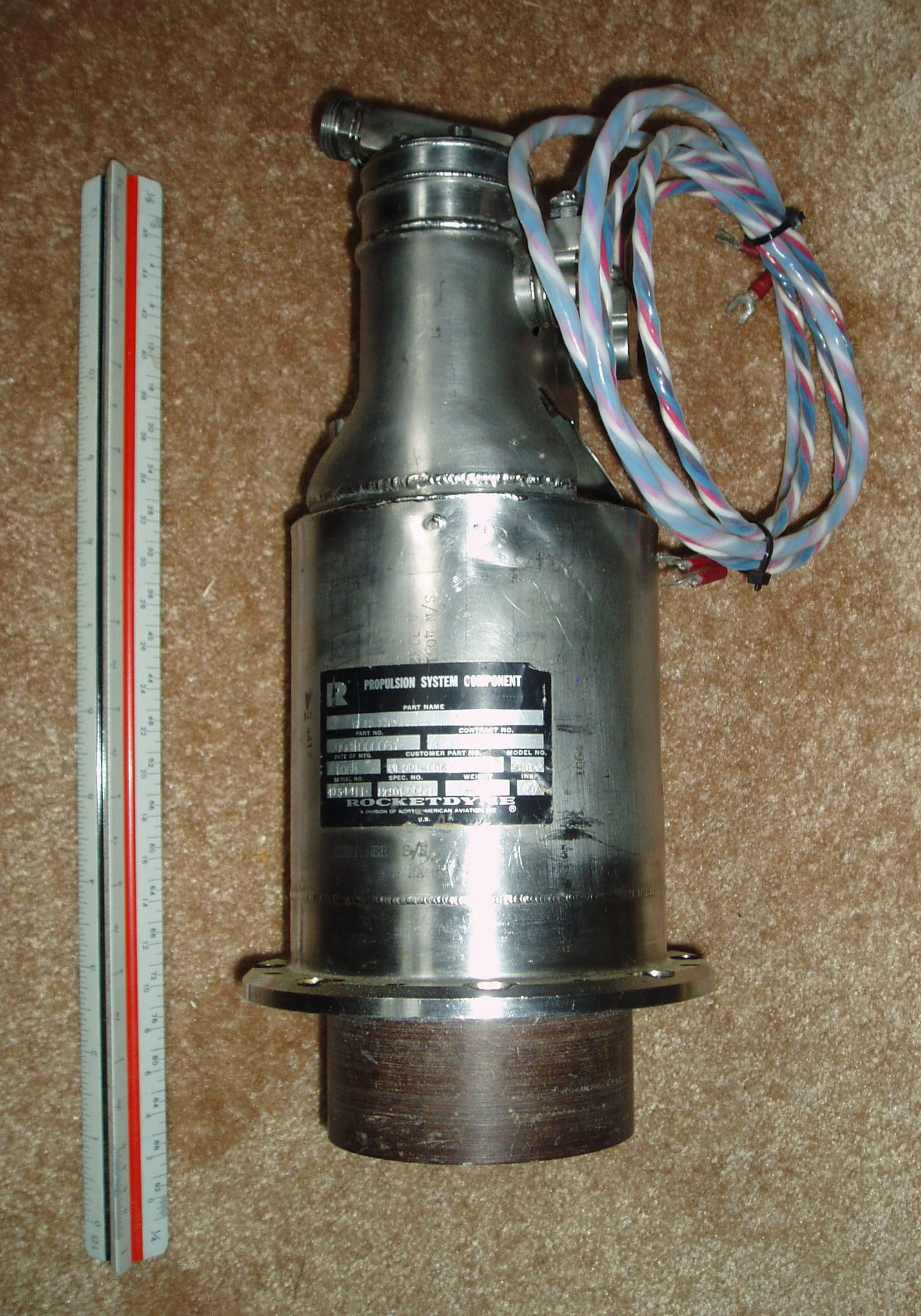
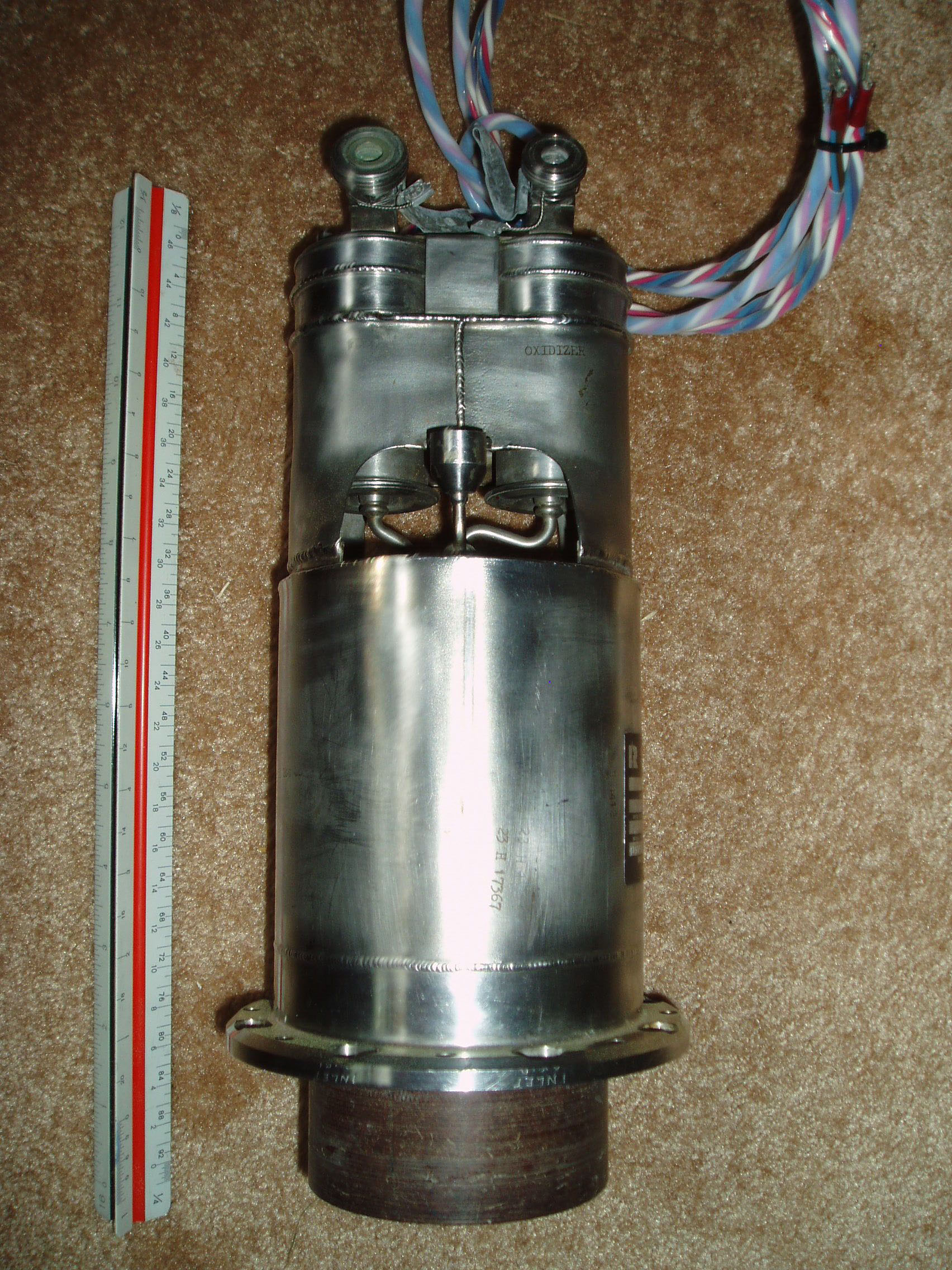
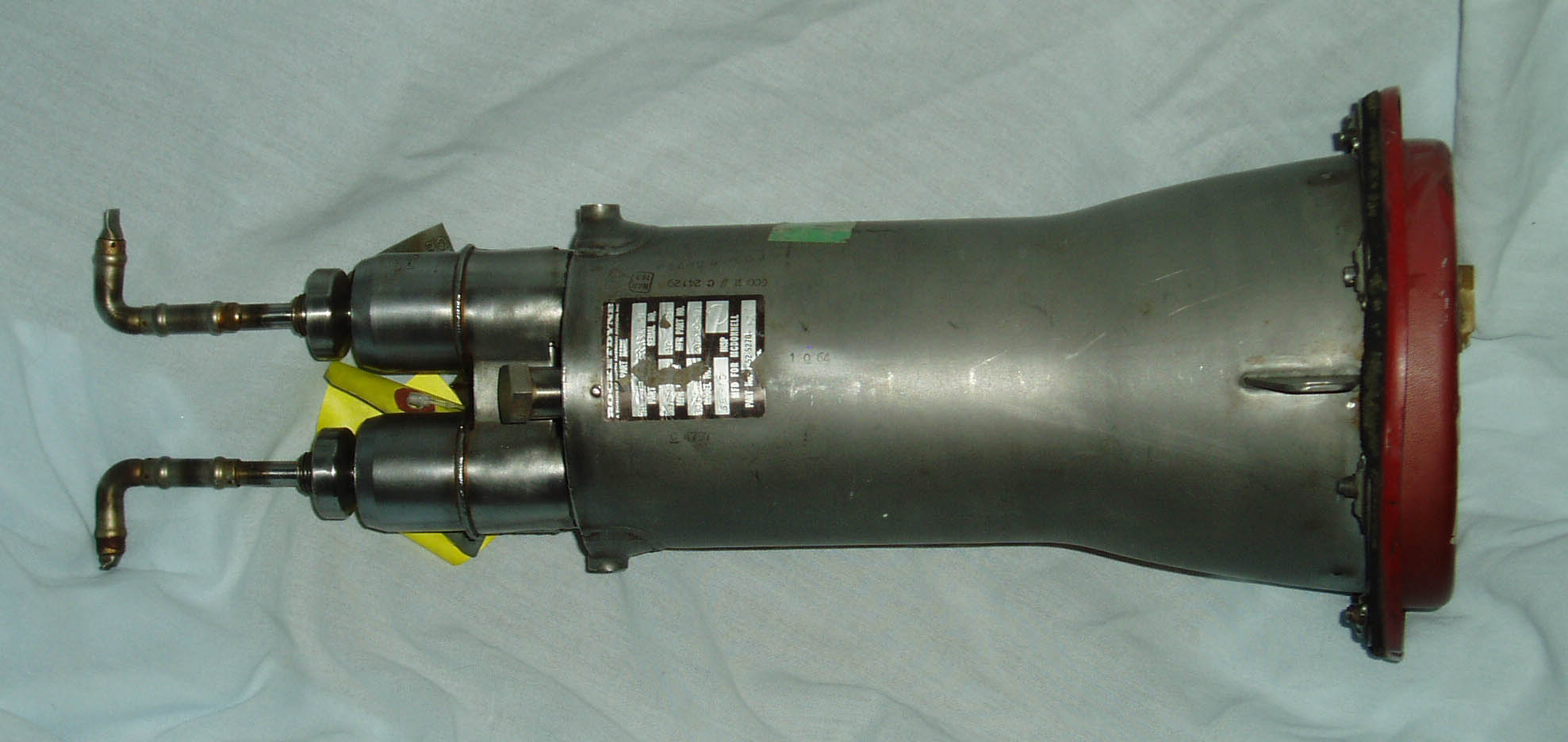
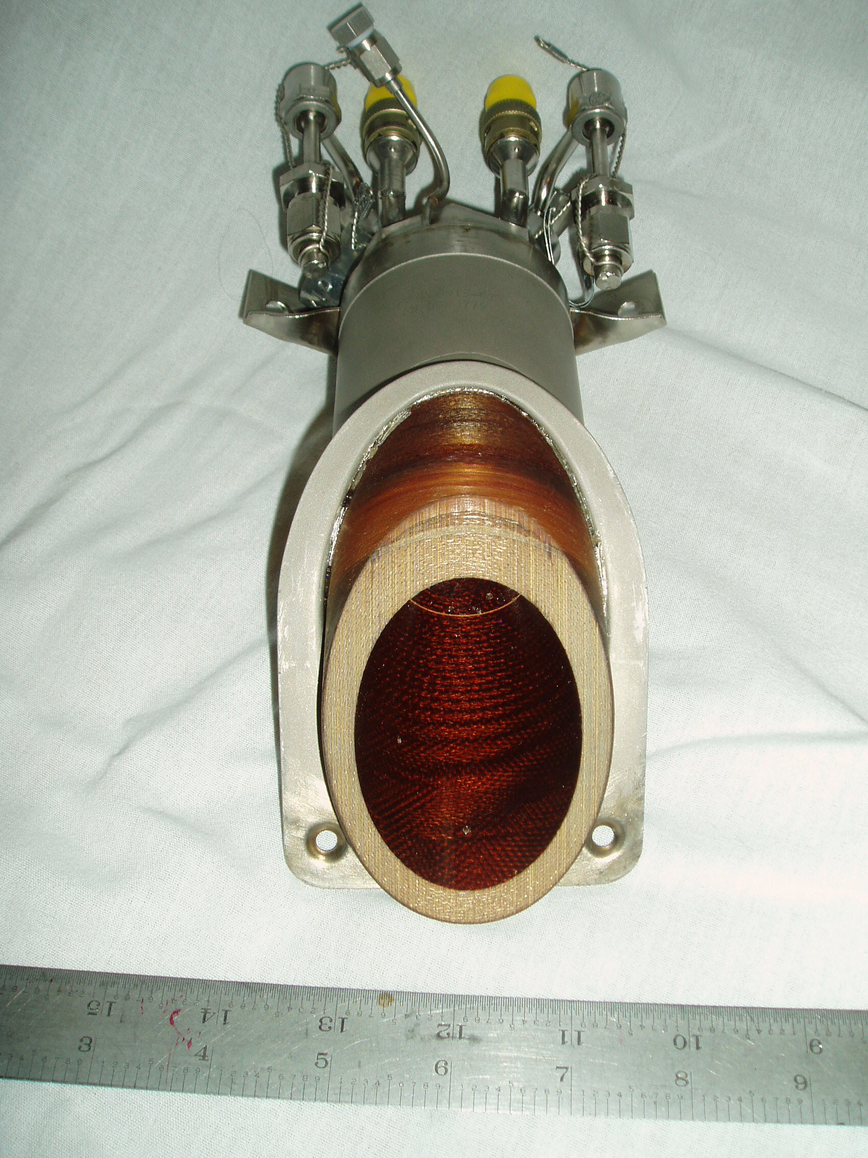
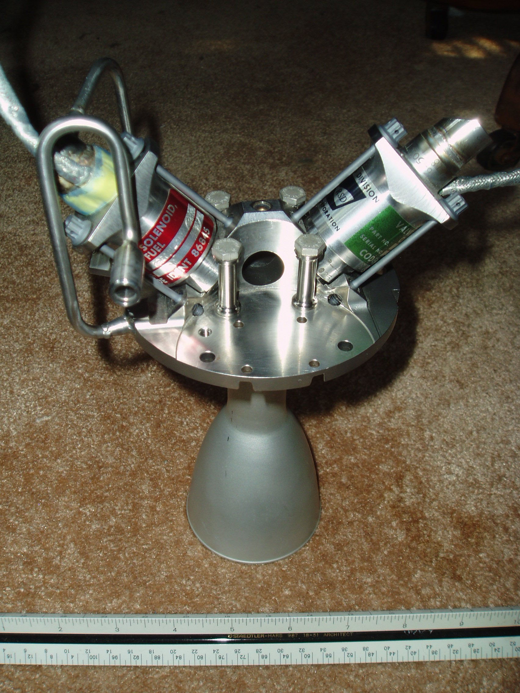
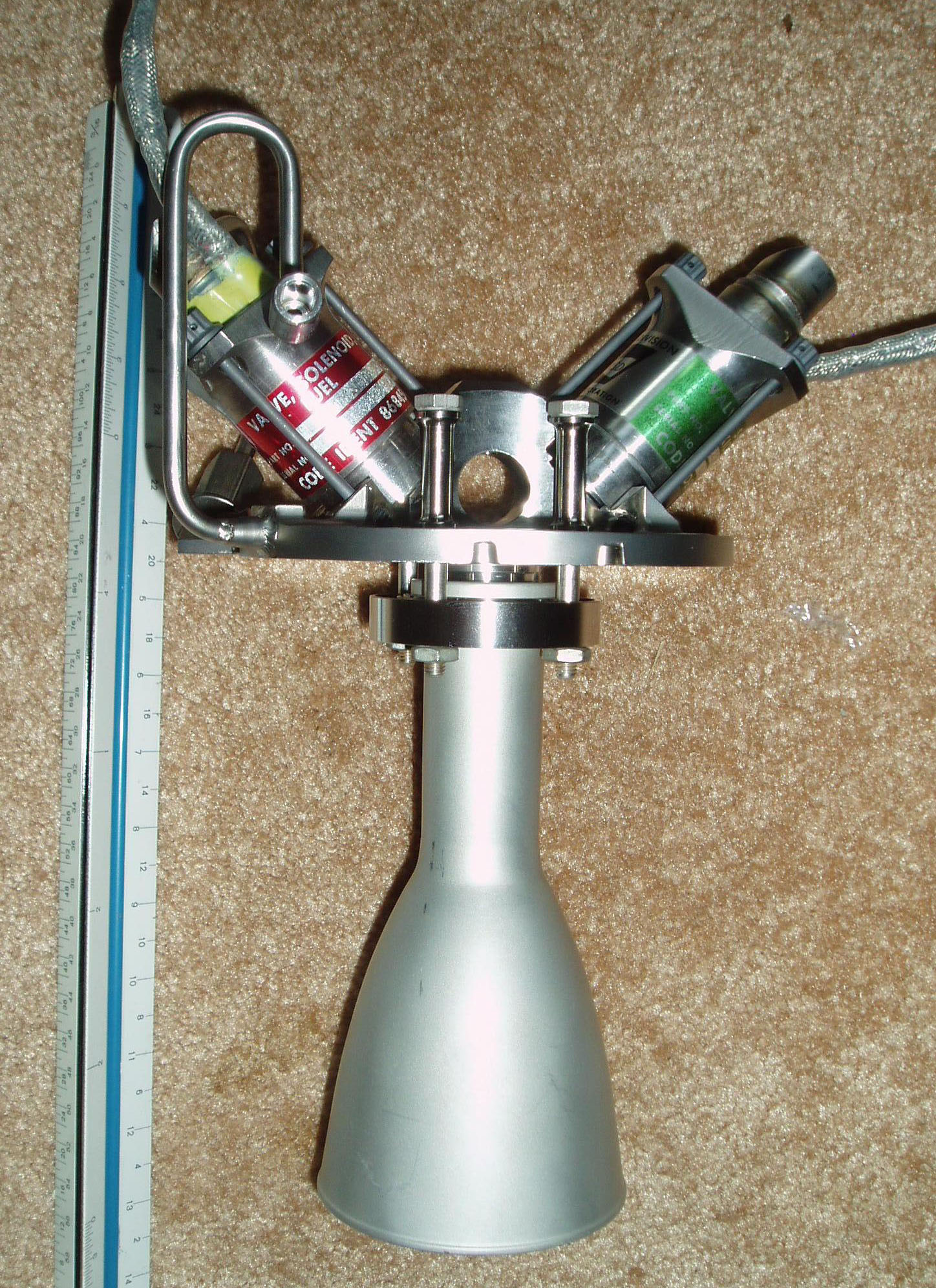
THIOKOL REACTION MOTORS DIVISION TD-339 VERNIER ROCKET ENGINE
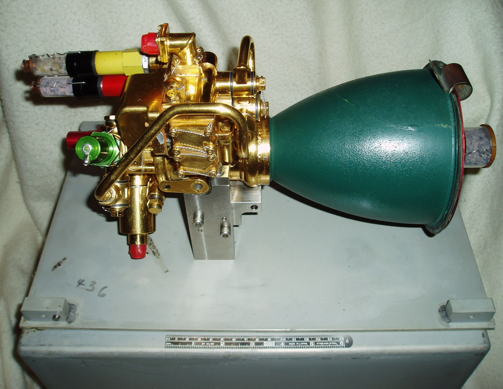
A Thiokol Chemical Corporation - Reaction Motors Division (RMD) TD-339 regenerative fuel-cooled Vernier thrust chamber developed for the Surveyor Lunar Lander program. Three of these gold-plated, engines were attached to the “knee” of each of the Surveyor’s three legs; 2 in a “fixed” configuration and the third (on Leg 1) gimbalable ± 6 degrees about an axis allowing its use for roll control of the spacecraft. The purpose of the Vernier was to provide propulsive power for mid-course correction maneuvers, attitude control before and during the main terminal descent phase from 66 nautical miles altitude above the lunar surface to touchdown, and prime retro power after the main solid-fuel Thiokol retro was jettisoned from the Surveyor spacecraft.
The 100 pound engine utilized hypergolic Monomethyl Hydrazine Hydrate (MMH-H2O) as the fuel and mixed oxides of nitrogen - Nitrogen Tetroxide with 10 percent Nitric Oxide (MON-10) as the oxidizer at a maximum chamber pressure of 250 psia. NO was added to the oxidizer to reduce the freezing point.
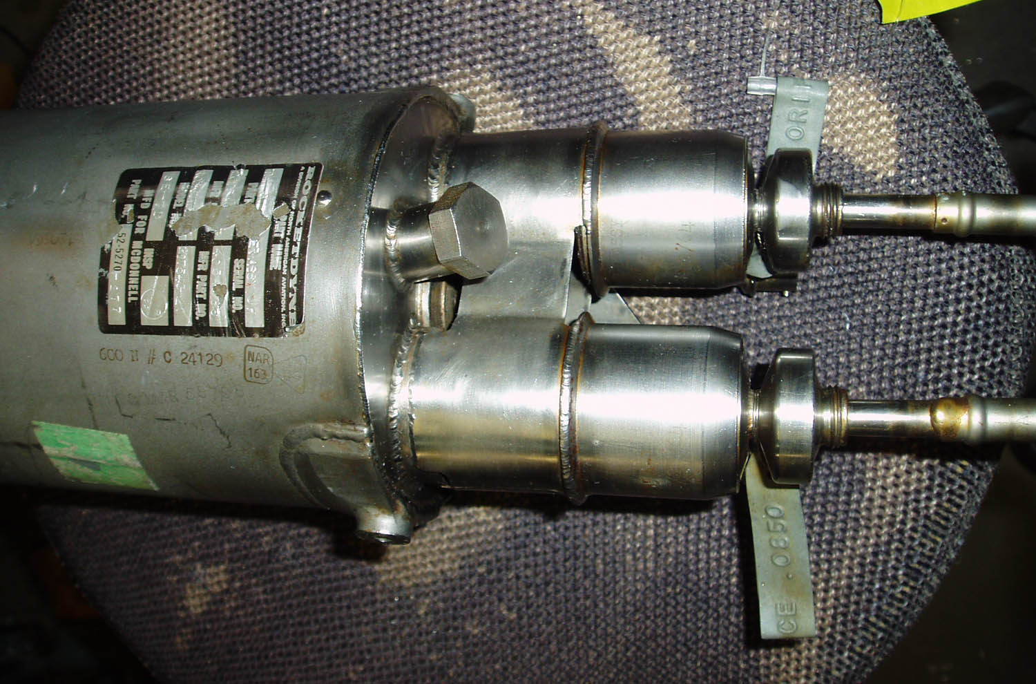
Assembly consists of a linked upstream throttle valve (each engine was individually throttleable between 30 and 104 pounds), a regeneratively fuel-cooled cylindrical thrust chamber of concentric stainless steel with vortex injector and ceramic liner of Zirconium Oxide (Rokide-Z), Silicon Carbide insert throat block and a molybdenum nozzle extension; collectively these engines subassemblies implemented a “Voramic Chamber” concept which was introduced by RMD to mitigate heat transfer issues associated with potential boiling and decomposition of the propellant applied to regeneratively cool the Vernier. A fuel regulator also maintained constant high pressure to inhibit fuel boiling within the chamber cooling jacket. The fuel itself was chosen for its thermal stability so it could operate through the full range of Surveyor’s throttling modes. The gold plating seen on the exterior of the engine is 0.0001 inch (.00025 cm) thick and was applied for rejection of thermal/cosmic radiation from the sun.
This artifact is displayed in its transport case mounting, exactly as it would have been received by the Jet Propulsion Laboratory (JPL) from the manufacture (RMD) with installed desiccant plugs for shipment.
The Surveyor project was conceived by JPL scientists primarily as a series of robotic precursor missions to prepare the way for human landings and exploration on the lunar surfaces during the Apollo project. The Vernier Propulsion System (VPS) was one of the most difficult developments undertaken by the Surveyor project. Seven Surveyor missions were conducted between May 1966 and January 1968, two of which (Surveyors 2 and 4) were not successful. A significant achievement occurred in 1967 with the TD-339 enabling the first flight from the Lunar Surface with the lift off of Surveyor 6 as it performed a 2.5 meter “hop” maneuver (the maneuver was executed to observe surface disturbances produced by the initial landing and the effects of firing rocket engines close to the lunar surface – important information required to properly engineer the Apollo Lunar Module Descent Engine).
Ultimately RMD's (Thiokol) demise in the small thruster market has been attributed to the complexity of a combination regenerative/radiation cooled motor. Other manufacturers developed 100% radiation cooled motors utilizing Niobium (Columbium) as the chamber material.

Surveyor 3 at Oceanus Procellarum (Ocean of Storms) - Apollo 12 LM Intrepid in the Background)
Atlas Vernier Gimbal View 2

Atlas Vernier Gimbal View 3
Atlas Vernier Gimbal View 4
Ungimbaled LR-101 Atlas Vernier TCA Set
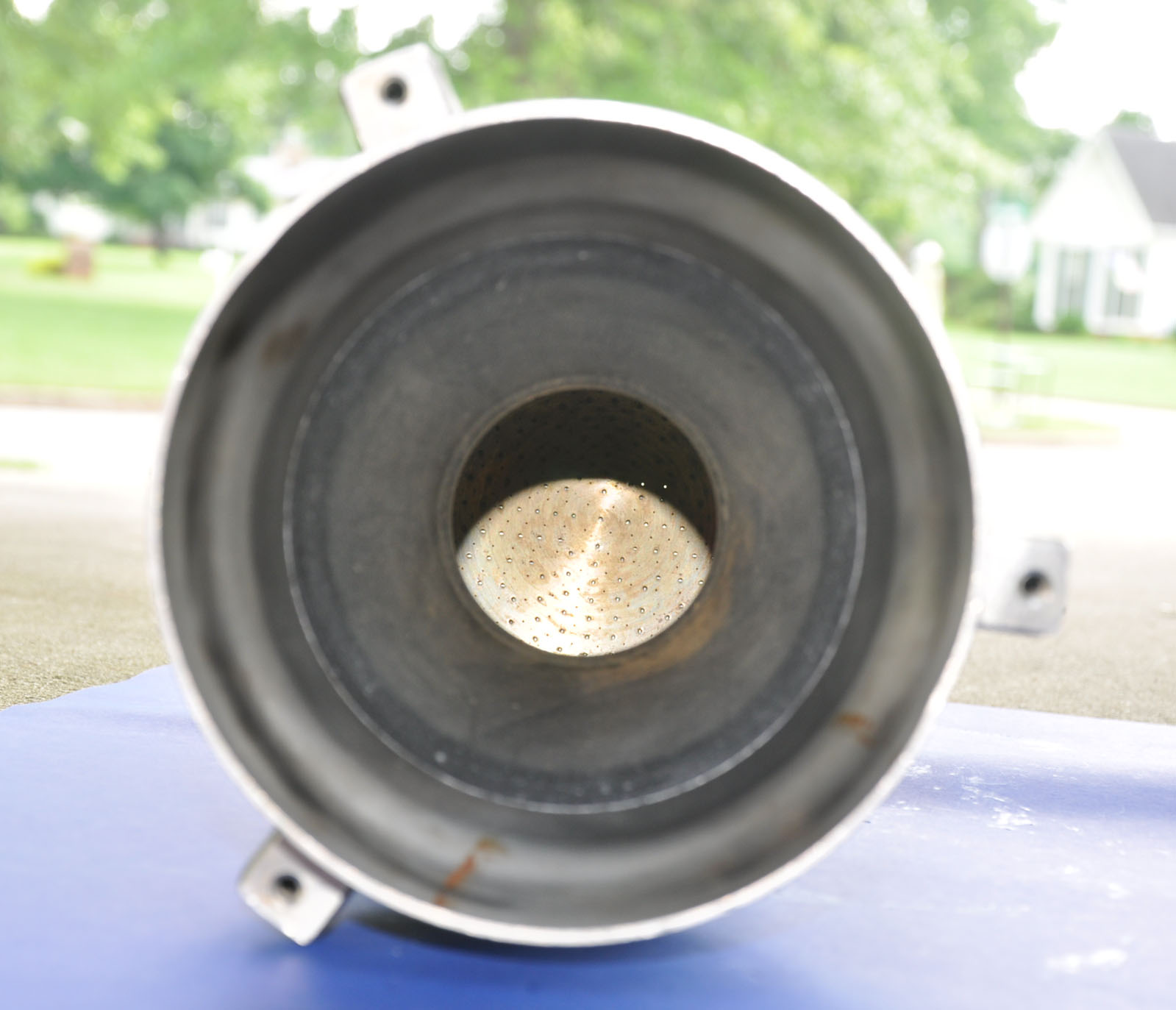
Integrated Injector/Lox Dome Assembly
Internal View LR-101 Thrust Chamber
Delta Thor ICBM Vernier Gimbal (Undergoing Restoration)
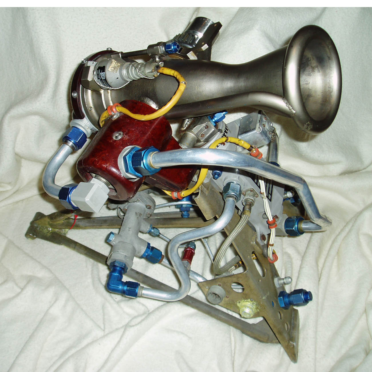
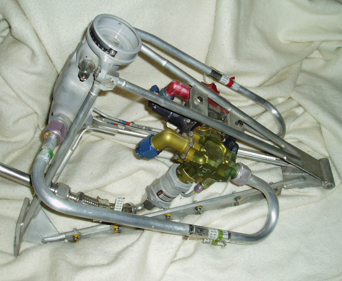
ROCKETDYNE LR-101 VERNIER
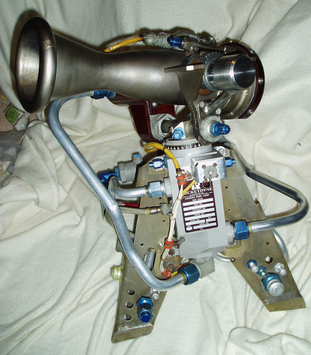
An LR101-NA Vernier rocket engine assemblage manufactured by ROCKETDYNE Corporation for installation onboard an Atlas SM-65 ICBM (Atlas “A”/XLR 89 NA-1). These engines were employed in various configurations to provide attitude (roll, pitch and yaw) control onboard the Mercury-Atlas, Atlas, Thor ICBM, Delta propulsion systems. A fixed-thrust, single-start, liquid bipropellant engine producing of maximum of 1000 pounds of thrust (nominal seal level), the engine design allows postoperative purging, regenerative cooling, thrust chamber gimbaling, and full-thrust runs of 325 seconds duration. It has a dry weight of 54 pounds and measures approx 28 x 27 ¼ x 20 inches (normal gimbaling arcs included). Designed propellant mixture is combination RP1 (highly refined liquid Kerosene) and LOX (liquid oxygen).
The engine consists of a thrust chamber assembly (a steel double-walled structure with a copper spiral regenerative cooling coils between the inner and outer walls), a pneumatically operated propellant valve with a valve position-indicating switch, an electrically fired igniter assembly, a pneumatically controlled oxidizer bleed valve, a fuel manifold pressure switch, a manifold gimbal assembly, propellant orifices, and pneumatic purge check valves. These components along with interconnecting electrical cabling and tubing assemblies are fixed in position on a welded tubular engine mount.
Gimbaling is facilitated via a pitch gimbal shaft, which provides for movement of the thrust chamber through a pitch-roll correct arc of 70 degrees on either side of the neutral position; and a yaw gimbal shaft which permits movement of the vernier thrust chamber through a yaw correction arc of 30 degrees (outboard) and 20 degrees (inboard) of the neutral position. In addition to performing the thrust direction gimbal function, the yaw shaft serves as a manifold for passage of fuel and oxidizer to the thrust chamber.
A variant of the gimbal is shown at the lower left and was designed for application on Delta-Thor ICBM.
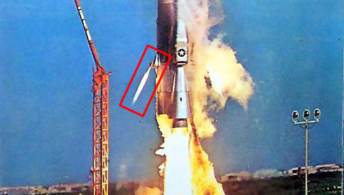
Mercury Atlas Launch with LR-101 Gimbaled Vernier providing vehicle attitude control
AEROBEE 100 Injector
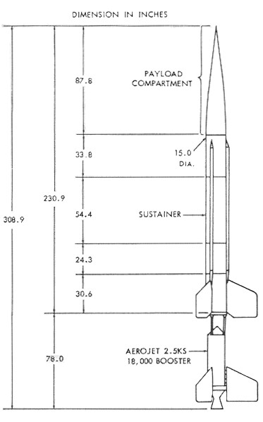
AEROBEE 100 Drawing
AEROJET AEROBEE 100 SUSTAINER ENGINE
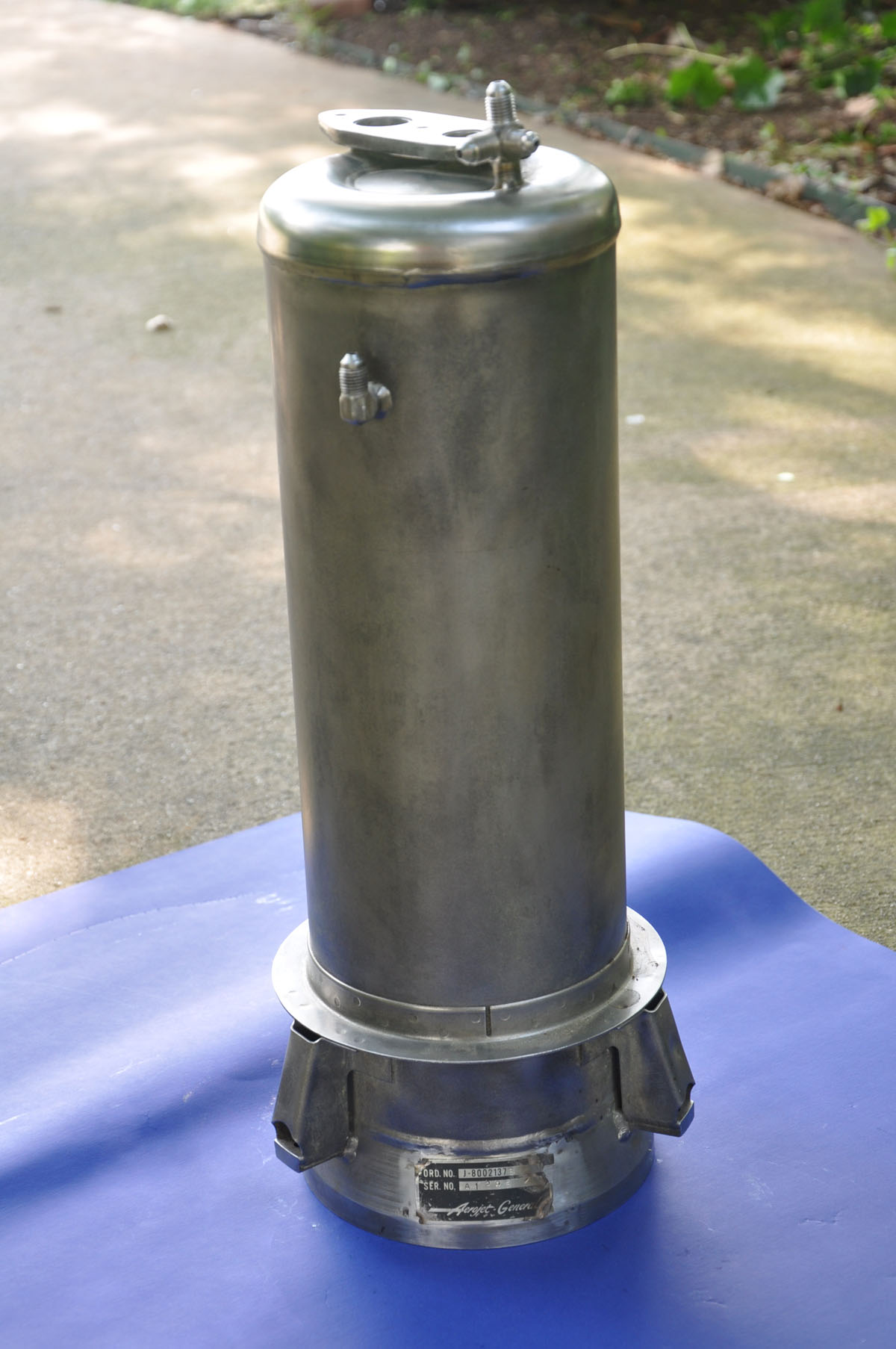
An AEROBEE 100 liquid fueled rocket sustainer (designated 45AL-2600) derived from the WAC Corporal surface to surface missile propulsion system.
The Aerojet General Aerobee 100 was the first purpose-designed American high altitude sounding rocket and the precursor to the Aerobee 150. It used an entirely different sustainer engine that burned IRFNA (Oxidizer) and RP1 (Fuel). Engine starting was accomplished with the hypergolic reaction between IRFNA and a starting slug of UDMH. The engine produced a nominal thrust of 2,600 pounds for a duration of 40 seconds. The rocket was capable of a peak altitude of 92 miles carrying a 40 pound payload. There were only 20 Aerobee 100 rockets produced. The Aerobee 100 used the same 2.5KS-18000 solid propellant booster as the Aerobee 150.
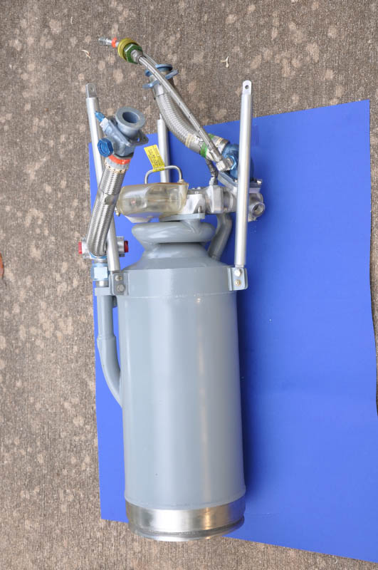
AEROBEE 150 Obverse View
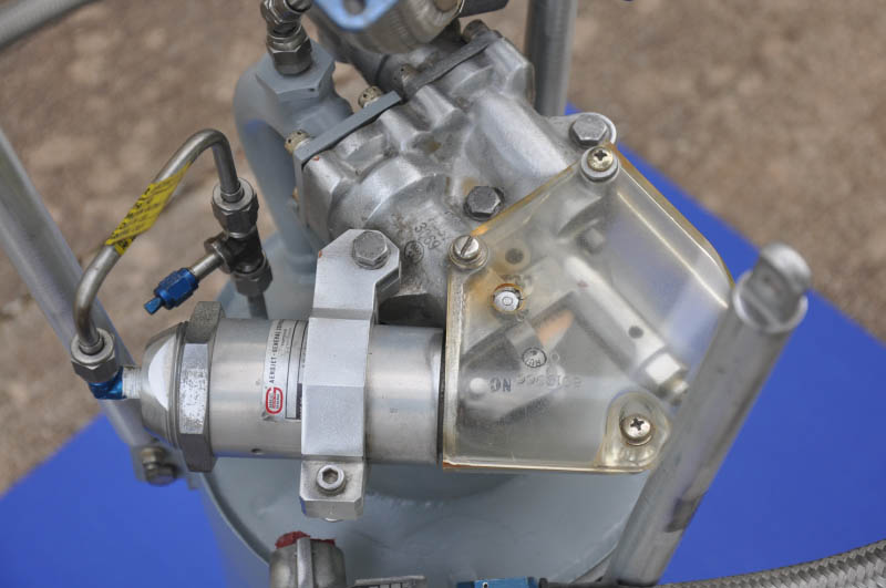
AEROBEE 150 Injector
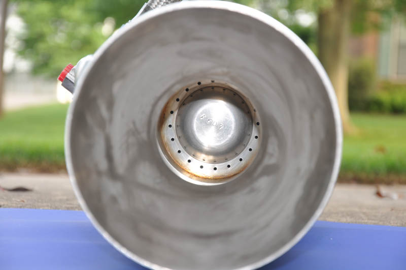
AEROBEE 150 Injector (Throat View)
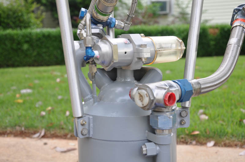
AEROBEE 150 Regenerative Feed Line
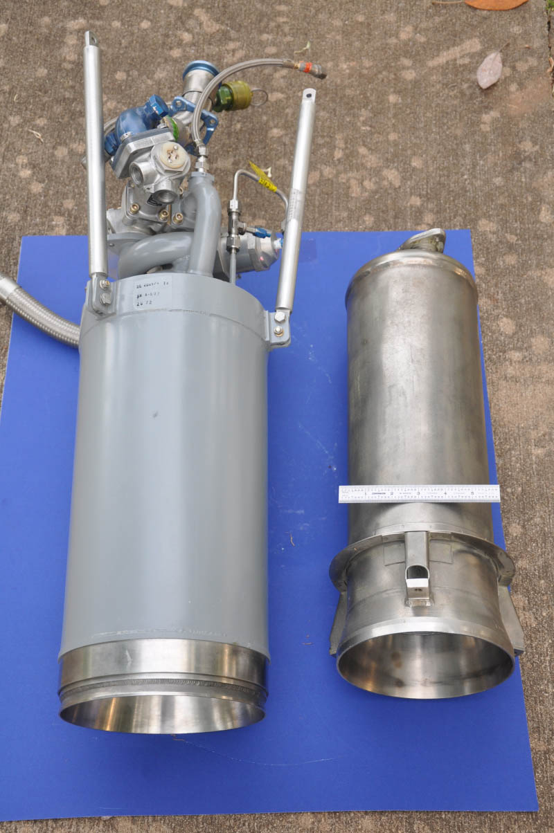
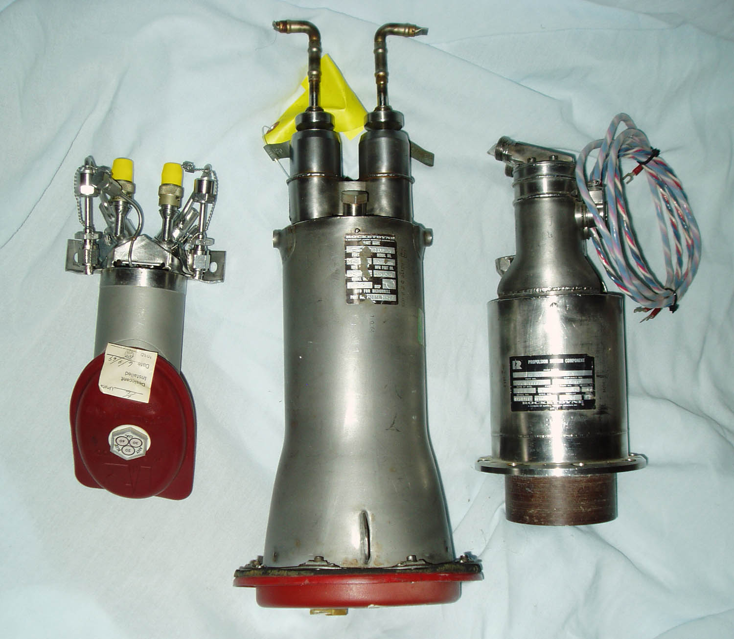
Comparison of Aerobee 150 (left) and Aerobee 100 (right) sustainers.
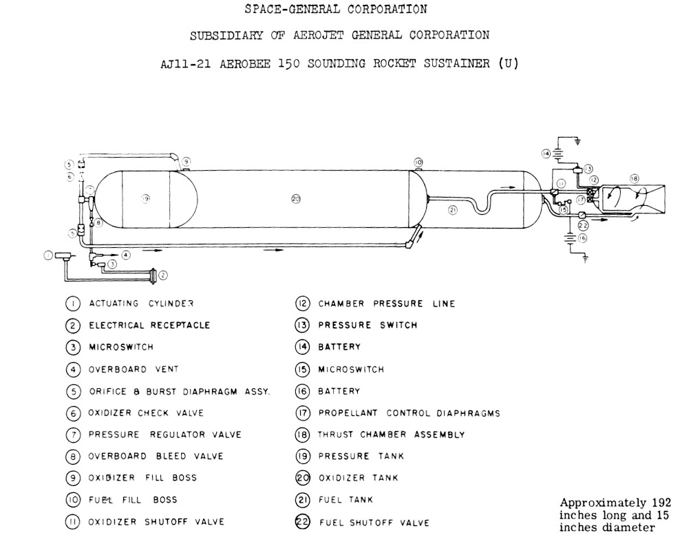
AEROBEE 150 SCHEMATIC
AEROJET AEROBEE 150 SUSTAINER ENGINE

An AEROBEE 150 liquid fueled rocket sustainer (designated AJ11-6) rated at 18kN (4,100 lbs) for 42 seconds. The Aerojet General Aerobee was the first purpose-designed American high altitude sounding rocket. The Aerobee 150 was for many years the standard American upper atmosphere research vehicle employed between 1947 and 1985. Over 1,000 vehicles were launched with a lift capacity of 40-300 pounds to altitudes of up to 300 miles. Lifts included instrumentation and a program of flying biological test subjects.
The same engine was used in the Nike Ajax Sustainer with a slightly different mounting structure. The Aerobee 150 engine produced a nominal thrust of 4100 pounds, had an Isp of 198 seconds using Analine and IRFNA as fuel and oxidizer respectively with a nominal chamber of 324 psia. The pressurant was helium. Both the oxidizer and fuel valves were poppet type valves, operated by a single actuator by way of a linkage arrangement.
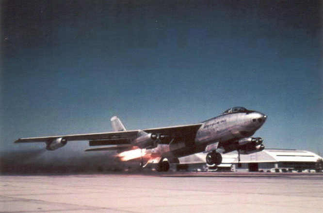
B-47 with RATO Take-Off
B-47 RATO
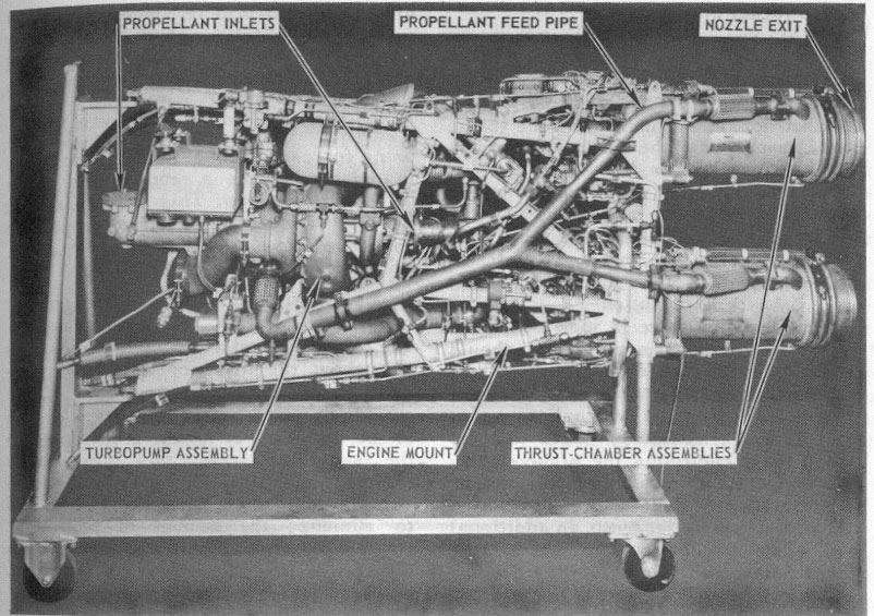
AEROJET B-47 ROCKET ASSISTED TAKE OFF ENGINE (YLR-45-AJ1)
An Aerojet YLR-45-AJ-1 B-47 RATO Engine developed in 1948 for the USAF. The B-47 Rocket Assisted Take Office (RATO) was a turbopump driven engine that utilized nitric acid and kerosene for propellants. A similar engine, designated the YLR-47-K-1 was produced during a competitive contract by the M.W. Kellogg corporation. 4 mounted RATOs on the B-47 provided a total of 20,000 pounds thrust of 60 second duration.
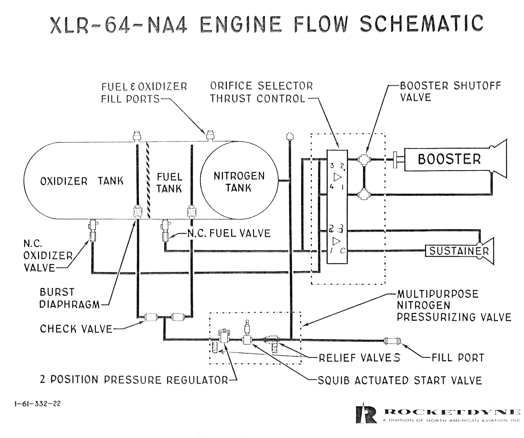
LR-64 Engine Flow
LR-64 Sustainer

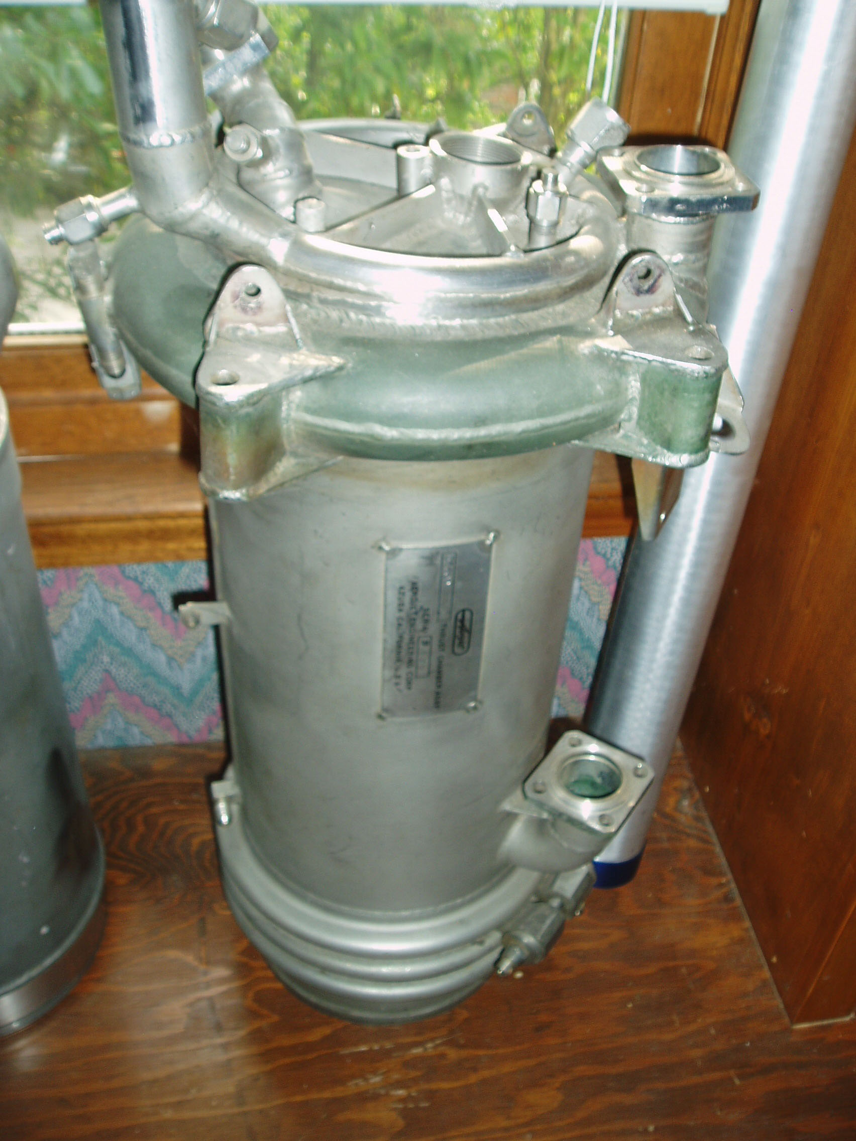
LR-64 Booster Chamber

AQM-37 TARGET DRONE
ROCKETDYNE P4-1 BIPROPELLANT ENGINE
ROCKETDYNE P4-1 (LR 64) bipropellant pressure fed engine developed for the AQM-37 Jayhawk supersonic target drone. The engine burned a combination of hydrazine and red fuming nitric acid for a rated thrust of 1,000 pounds and could support altitudes up to 80,000 feet.
The AQM-37 series drones were utilized by the Navy to emulate high speed enemy aircraft and missiles for engagement by U.S. fighters during live fire exercises.
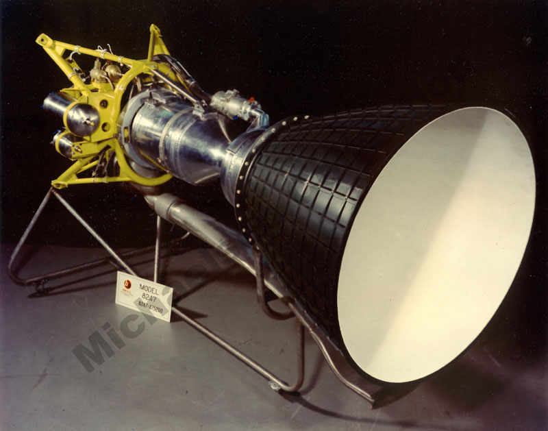
AGENA ROCKET ENGINE
TEXTRON BELL AGENA LOWER THRUST CHAMBER
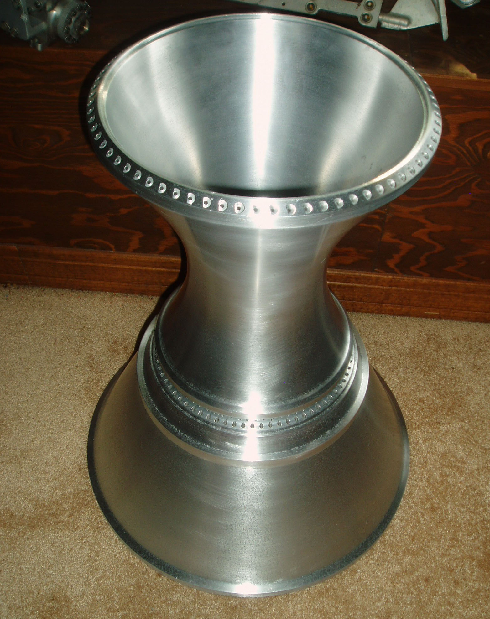
Aerospace Agena Thrust Chamber, Model 8096 lower thrust chamber. The restartable engine, produced from 1963 through 1987 burned a hypergolic propellant mixture of nitrogen tetroxide (nitric acid) and unsymmetrical dimethyl hydrazine (UDMH) and had a rated burn time of 265 seconds. This derivative of the Agena was employed onboard Thor, Atlas and Titan. Thrust chamber construction was notable for its all aluminum composition and was regeneratively cooled through the application of oxidizer into the drilled channels which permeated the entire assembly.
The Agena engine was known as the "workhorse of the space age". Its versatility and reliability made it one of the world's most flown and most successful liquid propellant rocket engines. It was fired more then 600 times with a flight demonstrated reliability greater than 99.7 percent.
Significant achievements:
- First engine used to power a U.S. spacecraft to circular orbit
- Placed first nuclear reactor in space
- First to conduct U.S. manned orbital rendezvous and space docking (Gemini program)
- First to propel a spacecraft on a successful Mars and Venus flyby
- First to propel man into high earth orbit
VIKING THRUSTER

VIKING LANDER
ROCKET RESEARCH P-95 MD-50 VIKING THRUSTER
Rocket Research P-95 MD-50 monopropellant Hydrazine thruster developed for reaction control of the Viking Lander Aeroshell and Lander. The thruster was employed in two different configurations onboard the lander. As part of the reaction control system, four three-engine clusters provided impulse energy for deorbit and attitude control through entry. The thruster was also used in the Terminal Descent System and were integrated as part of the protective shroud (AEROSHELL) which surrounded the lander.

SE-8 data plate
SE-8 INJECTOR
ABLATIVE NOZZLE
OBVERSE VIEW
APOLLO COMMAND SERVICE MODULE
ROCKETDYNE SE-8 ATTITUDE CONTROL THRUSTER
Rocketdyne SE-8 93 pound thrust bipropellant engine burning hypergolic monomehthyl hydrazine (MMH) and nitrogen tetroxide for propellants. Two sets of 6 engines each, were installed as part of the Apollo Command Module Reaction Control System. The CM RCS provided the impulse required for attitude control of the CM from the point of separation of the CM and the Service Module (SM) until the pilot parachute deployed.

Gemini SE-7
Injector Solenoids
Thrust Chamber Nozzle Showing Ablative Action Post Test-Fire
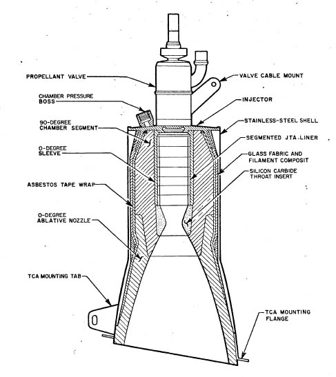
SE 7 Component Diagram
ROCKETDYNE SE-7 REACTION CONTROL ENGINE
Rocketdyne SE 7 Rocket Engine developed for application on the Gemini Spacecraft OAMS. The engine is rated for a specific impulse of 296 seconds/94.5 pounds thrust each in a vacuum environment. The ablatively cooled thrust chamber ran hypergolic propellants monomethylhydrazine (MMH) as fuel/nitrogen tetroxide (NTO) as oxidizer and has a total burn life of 425 seconds. The example displayed in this collection has been test fired.
The thrust chamber assembly consists of two fast-acting solenoid-type propellant valves, an injector, silicon carbide throat insert and an phenolic ablative body housed within a stainless steel outer shell. The propellant valves are electrically energized to open, allowing the hypergolic propellants to mix, burn and generate thrust.
The Gemini Orbit Attitude and Maneuver System (OAMS) SE 7 Engine System provided the propulsion for attitude and maneuver control of the Gemini Spacecraft while in earth orbit. The complete system included eight 25 pound thrust units for pitch, yaw and roll control; two 85 pound thrust units for aft spacecraft maneuver control and six 100 pound thrust units (similar to the example within this collection), two of which provided forward maneuver control, and four for lateral maneuver control.
Size Comparison - Rocketdyne SE-6, SE-7 and Apollo RCS SE-8
ABLATIVE NOZZLE
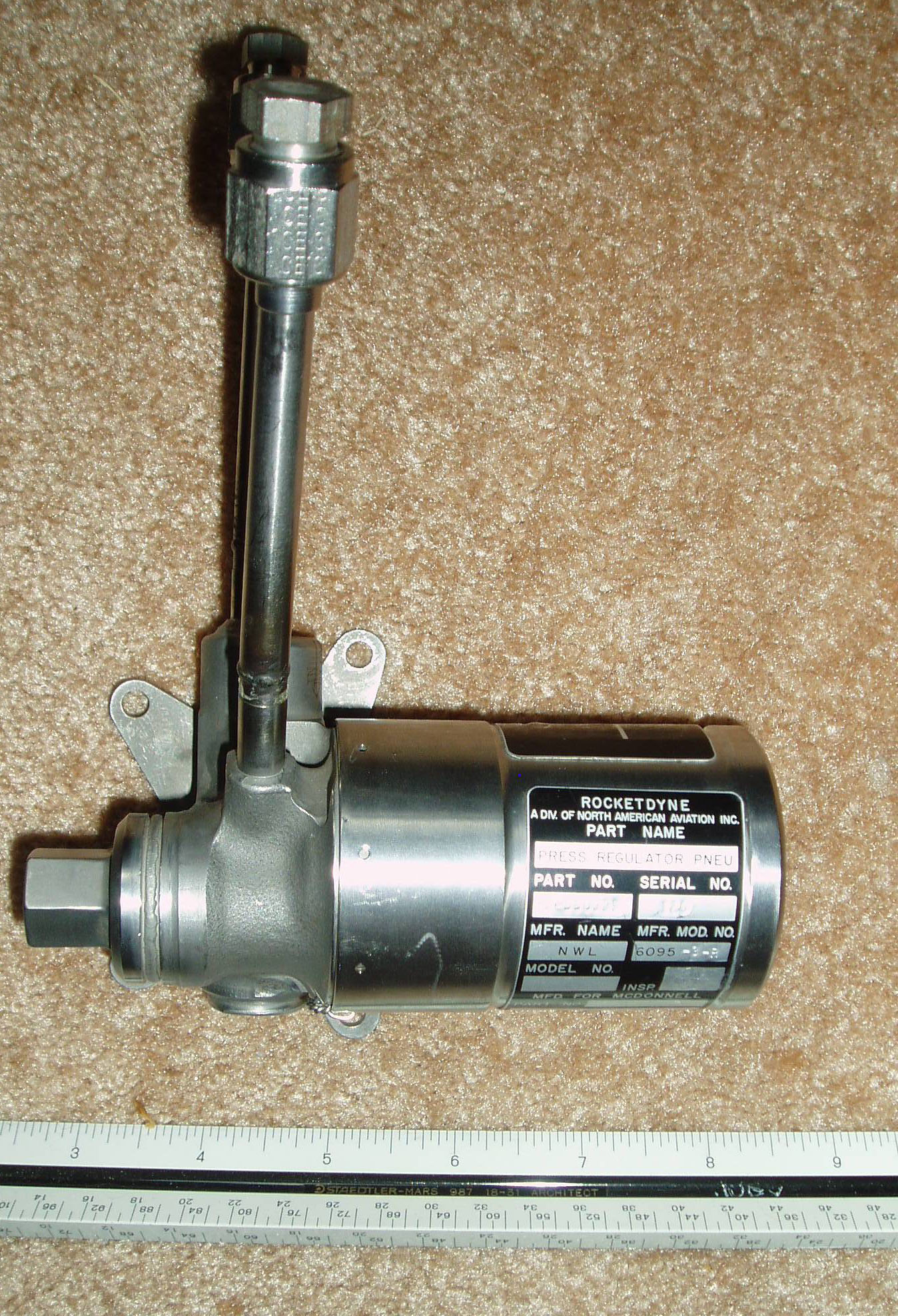
SE-6 PNEUMATIC PRESSURE REGULATOR (Helium)
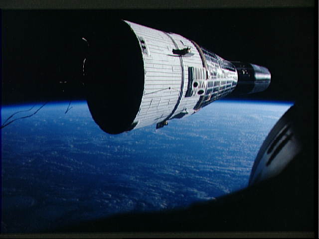
GEMINI VI (as seen from GEMINI VII)
ROCKETDYNE SE-6
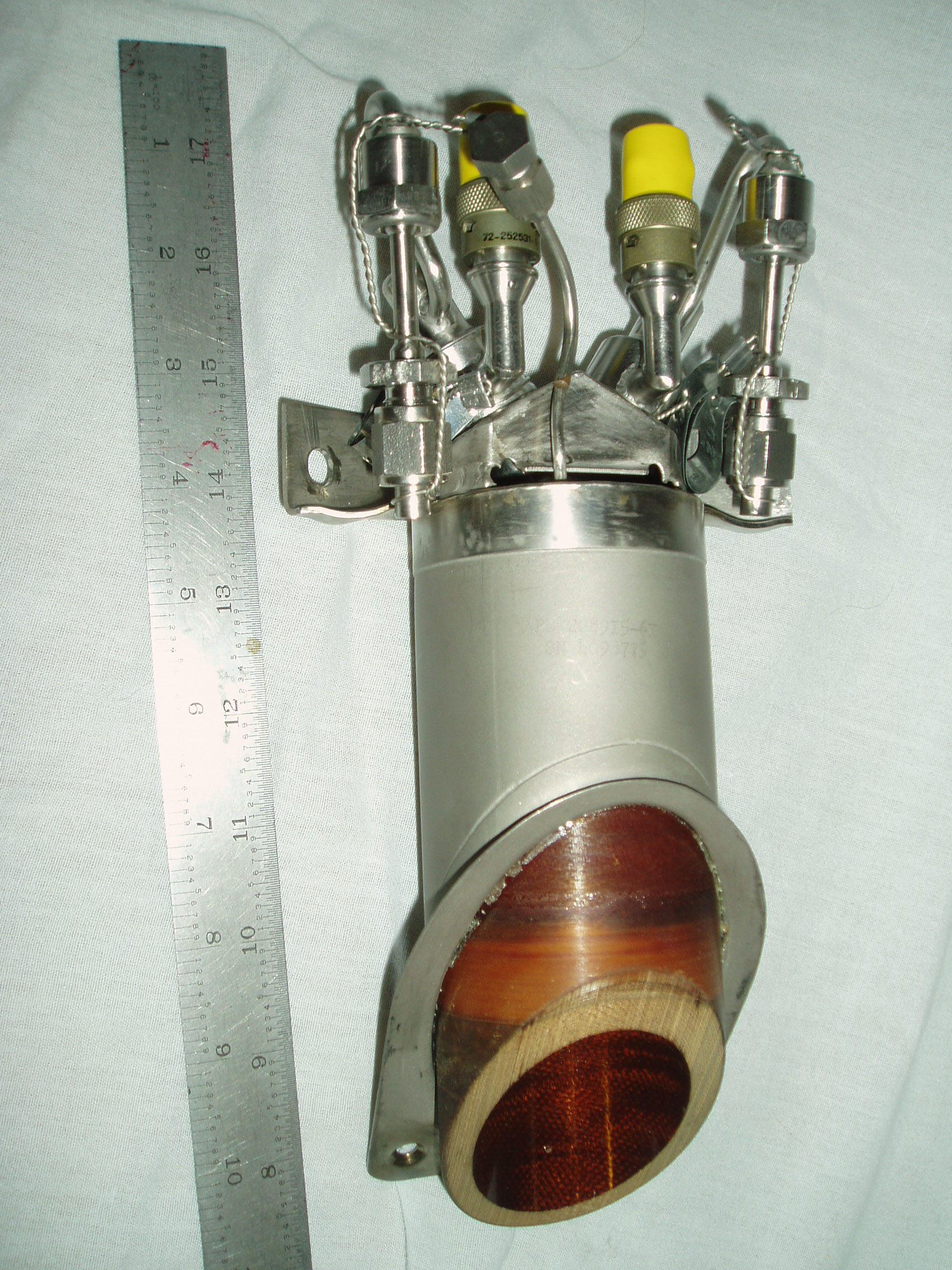
An SE-6 pressure fed bipropellant engine manufactured by ROCKETDYNE Corporation for installation onboard the Gemini spacecraft Re-Entry Control System (RCS). These thrusters utilized a hypergolic propellant combination of nitrogen tetroxide (NNH) as the oxidizer and monomethyl hydrazine (MMH) as the fuel. The ablatively cooled pulse-operated engine was rated for a total life span of 96 seconds while providing a vacuum thrust of 23.5 pounds/107 Newtons.
The thrust chamber assembly (TCA) consists of two propellant valves (fuel and oxidizer), injection system, calibrated orifices, combustion chamber and expansion nozzle. The fuel and oxidizer solenoid valves are the normally-closed quick acting type which open simultaneously upon command. The action permits fuel and oxidizer flow into the injector system. The injectors use precise jets to impinge fuel and oxidizer streams on one another for controlled mixing and combustion. The calibrated orifices are fixed devices used to control propellant flow. Hypergolic ignition occurred in the combustion chamber. The combustion chamber is non-regenerative; it is lined with ablative materials and insulation to absorb and dissipate heat and control external TCA wall temperature. When integrated to the Gemini spacecraft, the engine was installed within the RCS module mold line, with the nozzle terminating flush with the outer mold line. A total of (2) sets of eight SE-6 thrusters were paired at approximate radially symmetrical points on the RCS module in a location suitable to execute yaw/roll/pitch maneuvering and attitude control after loss (vehicle separation) of the Equipment Section/Orbit Attitude and Maneuver System (OAMS). The OAMS employed the more potent SE-7 (25, 85 and 100 pound) engines and provided primary attitude control during flight. Firing of the RCS TCA's were commanded via the Gemini spacecraft's Attitude Control and Maneuver Electronics System (ACME).
View 2
View 3
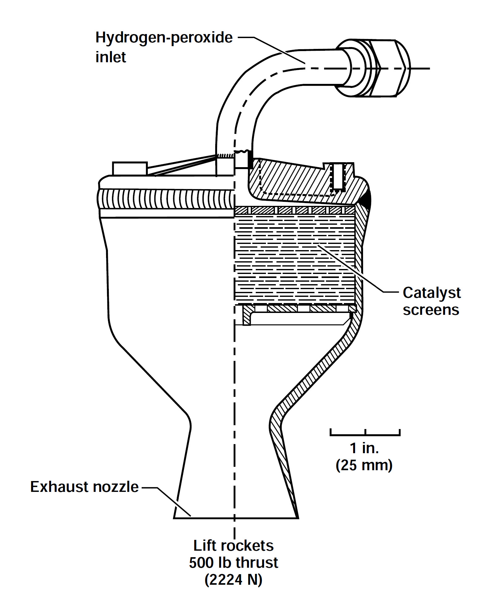
LLTV Lift Rocket Injector
LLTV Lift Rocket installed on jet engine gimbal ring (upper right)
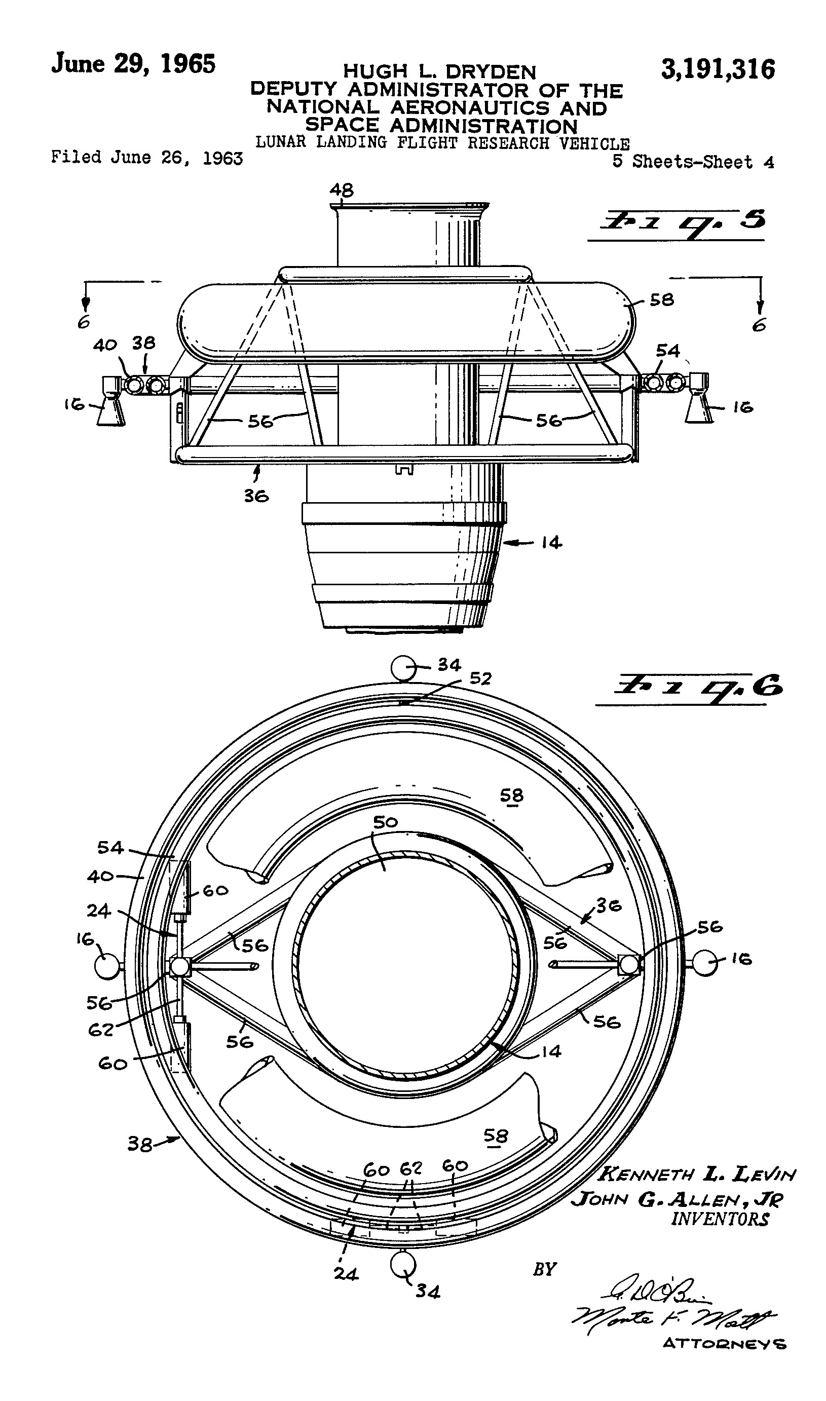
Figure from LLRV US patent showing the location of the two lift rockets (callout #16)
LLTV Lift Rocket
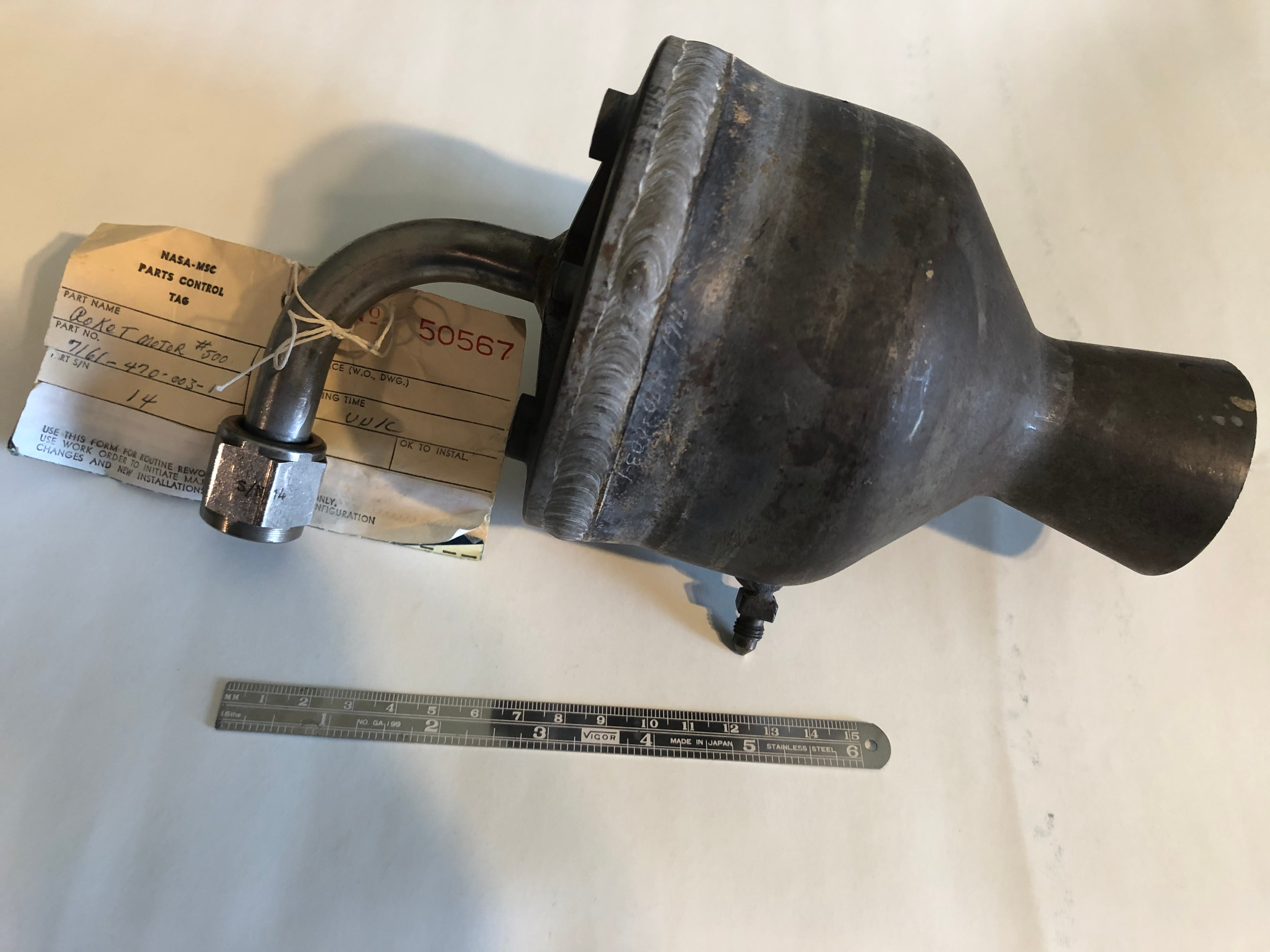
A Bell Aircraft hydrogen peroxide lift rocket from the Lunar Landing Training Vehicle. This motor had a variable thrust between 100 and 500 pounds.
The LLTV was the production version of the earlier and nearly-identical Lunar Landing Research Vehicle. It was a free-flying lunar landing simulator (nicknamed the "Flying Bedstead"), designed to duplicate the handling characteristics of the Apollo Lunar Module in the final moments of a lunar landing. The LLTV consisted of a trusswork frame supporting a cockpit; a vertically-mounted General Electric CF700-2B axial-flow, aft-fan jet engine mounted on a gimbal; 16 hydrogen peroxide attitude-control motors; two lift rockets; and the JP4 and peroxide tanks necessary to power its flight.
During most of a training run, the jet engine would support the entire weight of the LLTV. Once at the proper altitude, the pilot initiated the lunar-simulation mode. An on-board computer determined the vehicle's weight (based on the initial propellant load and subtracting the weight of the propellant consumed during the flight), decreased jet thrust to cancel out 5/6 of the vehicle's weight, engaged the two lift rockets to provide the remaining thrust necessary to support the craft, and entered an automatic stabilization mode where the computer automatically controlled the gimbal angle of the turbofan engine to provide a thrust vector correction for the aerodynamic forces that the vehicle experienced.
With the jet cancelling out 5/6 of Earth's gravity, the pilot was then able to vary the amount of thrust provided by the two fixed lift rockets to simulate the thrust of the Lunar Module's Descent Propulsion System engine in the Moon's 1/6 g environment and was thus able to practice the final lunar approach. The lift rockets also provided a horizontal thrust component for translation when the vehicle was tilted by using the attitude control system.
After the Apollo 11 landing, Neil Armstrong reported that "The LLTV proved to be an excellent simulator and was highly regarded by the astronauts as necessary to lunar landing preparation." After the completion of their missions, other astronauts agreed that the LLTV provided an excellent simulation of lunar conditions. Astronauts typically made 22 LLTV flights prior to their Apollo missions.

Lift rockets firing
The lift rockets were vertically trunnion-mounted on the ring frame member within the upper trusswork of two opposite landing gear legs immediately below gimbal axle housings. They were centered on the vertical center of gravity of the vehicle for dynamically stability.
Hydrogen peroxide was supplied to the lift rocket through piping at the top of the motor. As the nearly-pure hydrogen peroxide solution passed through silver screens at the forward end of the motor, it decomposed and turned into steam, which vented under pressure to provide thrust. Each motors' thrust could be varied from 100 to 500 pounds.
This particular lift motor was removed from LLTV2, which Armstrong and other lunar astronauts would have flown. This motor was removed from LLTV2 upon completion of the Apollo program and sent from Eillington Air Force Base (near Houston) to Edwards AFB for possible use in the H2F3 lifting body program. However, it is uncertain if it was ever used there.
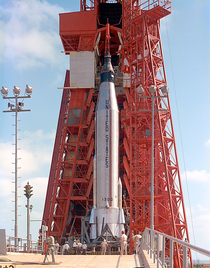
MERCURY ATLAS
Rocketdyne XLR-105 (MA-2) Subscale Sustainer
Rocketdyne XLR-105 (MA-2) subscale sustainer, utilized for engine design and prototyping. The sustainer was used in combination with the XLR-89 (variants) to propel the SM-65 series Atlas.

INJECTOR HEAD
LABEL PLATE
RADIATION NOZZLE
Single Propellant Valve employed on non Quad-Redundant configuration of C-1 (View 1)
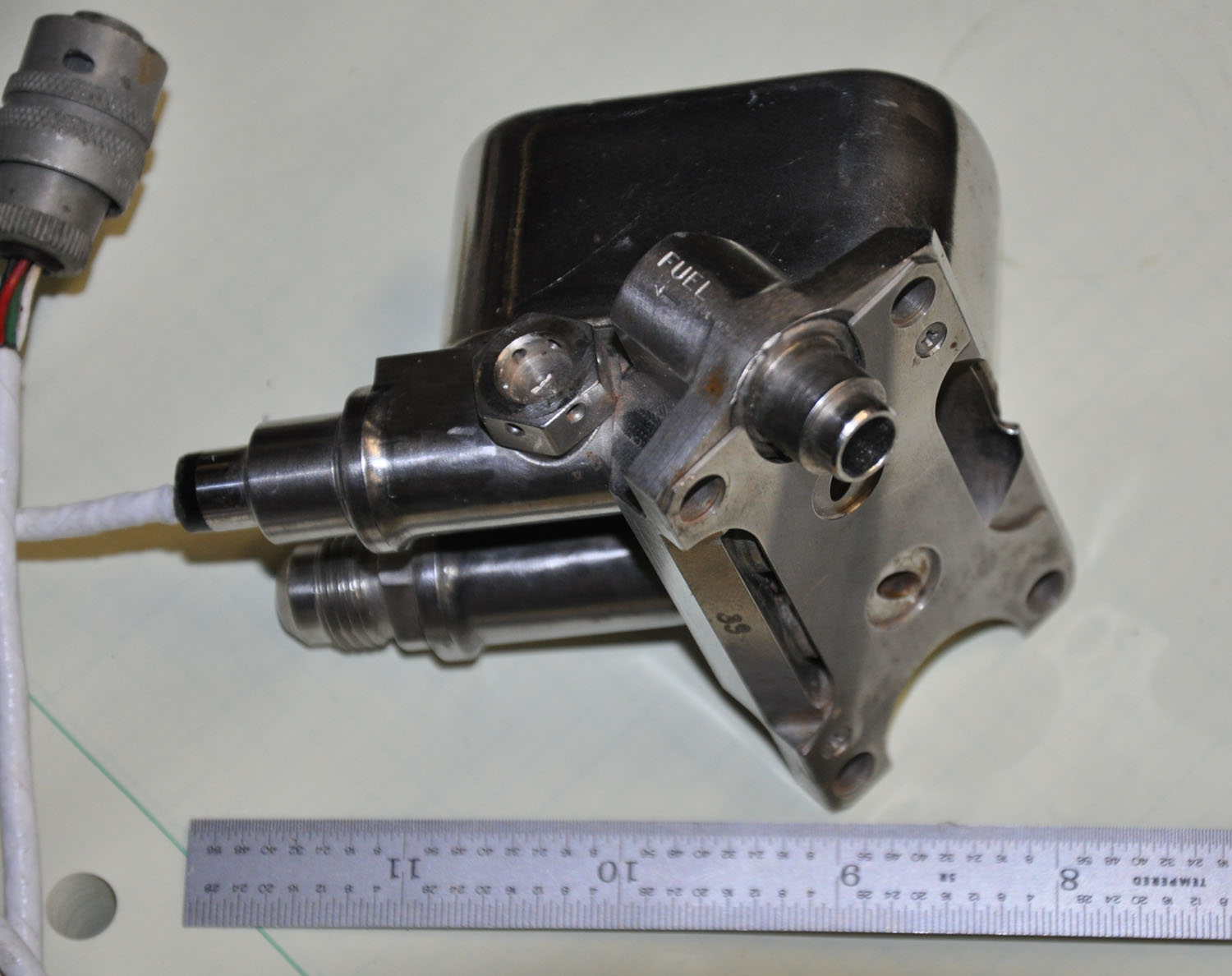
Single Propellant Valve employed on non Quad-Redundant configuration of C-1 (View 2)
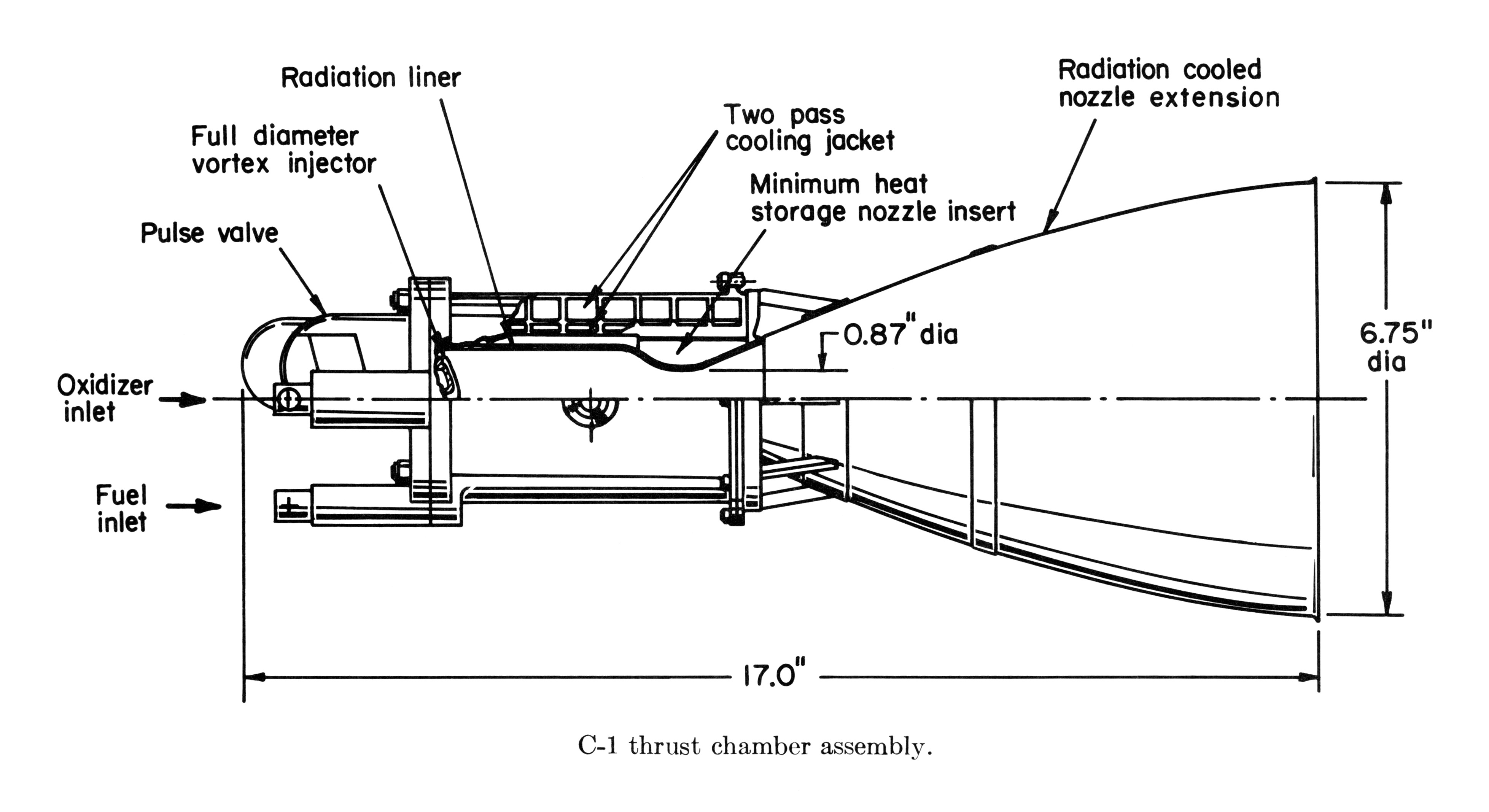
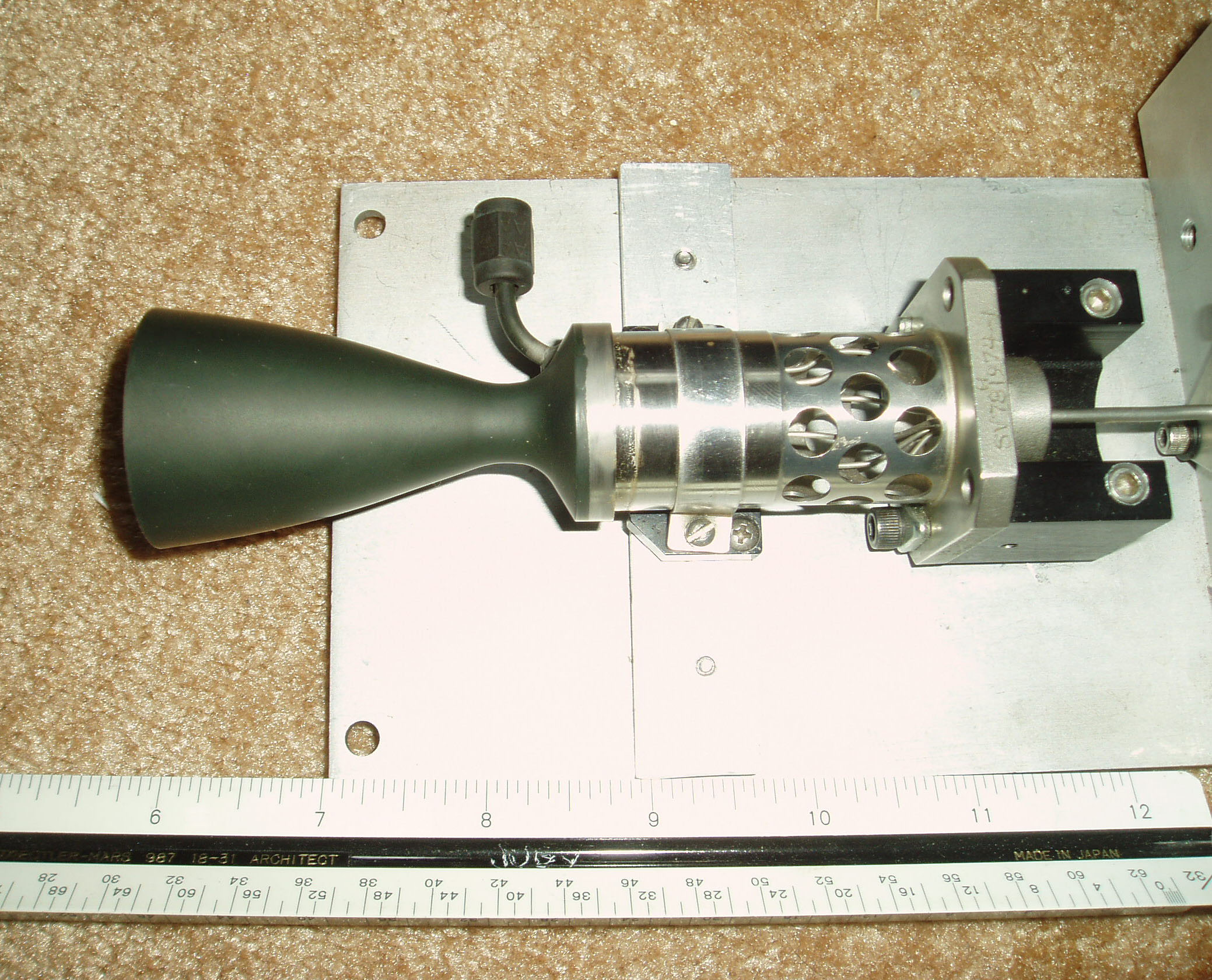
THIOKOL C-1 RADIAMIC ENGINE
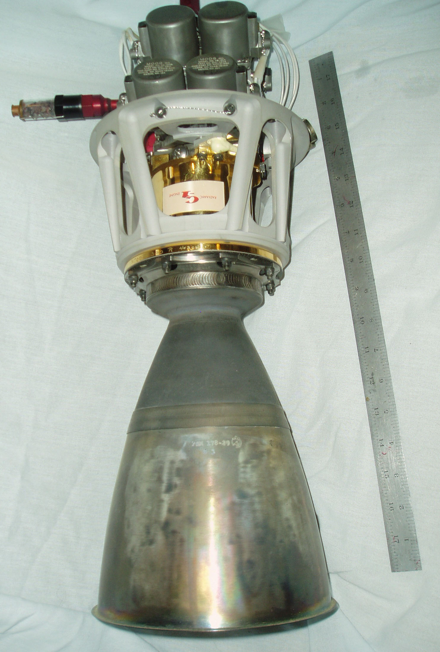
C-1 Radiamic Engine produced by Thiokol Chemical Corporation. A 100 pound fixed thrust liquid rocket engine developed for NASA's George C. Marshall Space Flight Center to meet space vehicle maneuvering and velocity control requirements of typical missions. The engine is a high-performance unit having unlimited restart capability for operation in steady state modes of 2 seconds to 2,000 seconds duration.
The C-1 engine was qualified with radiation-type nozzle extensions. However, the basic chamber is designed to accept interchangeable ablative extensions. Operating propellants are helium saturated nitrogen tetroxide (oxidizer) and monomethyl hydrazine (fuel). The engines can be equipped with quadredundant valves (as seen in this example) incorporating series-parallel propellant controls which offer valve redundancy features, or with mechanically linked bipropellant valves.
Thrust 100 pounds (vacuum); chamber pressure 96 pounds per square inch; specific impulse 292 seconds; wet weight as configured here with quadredundant valve is 16.25 pounds.

CENTAUR SHUTTLE RCS THRUST CHAMBER
HAMILTON STANDARD THRUST CHAMBER(S)
Linear and right-angle reaction control thrust chambers developed for the canceled Shuttle Centaur (G) Payload program.
Prior to cancellation, the Shuttle/Centaur vehicle was being developed as an expendable, cryogenic high energy upper stage for use with the National Space Transportation System (NSTS) as a modification of the highly successful Centaur stage, used extensively with the Atlas and Titan boosters since 1966 to launch planetary, geosynchronous and Earth orbital missions. Design changes included tank resizing to take advantage of the orbiter payload bay dimensions, provisions for physically adopting Centaur to the orbiter and accommodating safety requirements of the manned NSTS.
MARQUARDT R-1E INJECTORS
MARQUARDT R-1E BIPROPELLANT ENGINE
Marquardt Corporation model R-1E liquid hypergolic bipropellant rocket engine designed for classified space application. The engine was developed for high pulsing and steady state performances in combination with reliable, long-life operational characteristics. Propellants utilized were nitrogen tetroxide (oxidizer) hypergolically combined with monomeythl hydrazine (fuel) or Aerozine 50/50.
The engine was rated for a thrust of 22 pounds nominal (vacuum).